Power semiconductor device and manufacturing method thereof

A technology of power semiconductors and devices, which is applied in the manufacture of power semiconductor devices and the field of power semiconductor devices, and can solve problems such as long manufacturing cycle, hard reverse recovery characteristics of diodes, and severe fluctuations

Active Publication Date: 2018-02-06
SHANGHAI HUAHONG GRACE SEMICON MFG CORP
View PDF7 Cites 0 Cited by
  • Summary
  • Abstract
  • Description
  • Claims
  • Application Information

AI Technical Summary

Problems solved by technology

[0004] In the super junction process, due to the use of alternating P / N thin layers, the body diode of the power semiconductor device, that is, the diode formed between the P-type semiconductor thin layer and the N-type semiconductor thin layer, is at a lower reverse bias voltage such as 50 Vds will completely deplete the P-type semiconductor thin layer and the N-type semiconductor thin layer, which makes the diode have a very hard reverse recovery characteristic. This hard reverse recovery characteristic causes the recovery current of the device to change sharply. The fluctuations in the reverse recovery are severe, causing electromagnetic noise (EMI NOISE) in the circuit, which affects the work of other devices in the circuit. In this regard, power semiconductor devices are not as good as conventional MOSFET devices. Conventional MOSFET devices The drift region does not have a P / N thin layer structure, but the entire drift region is N-doped, because the depletion of the N-drift region of a conventional MOSFET device always expands with the increase of the voltage (Vds), reverse Softer recovery properties
[0005] In terms of process selection, multiple epitaxial growth and lithography and implantation processes have complex, long manufacturing cycle and high cost problems. In the trench filling process, it is necessary to deposit on a highly doped substrate before the trench process. The epitaxial layer with a thickness of tens of microns also increases the cost of the process

Method used


Image

  • Power semiconductor device and manufacturing method thereof
  • Power semiconductor device and manufacturing method thereof
  • Power semiconductor device and manufacturing method thereof

Examples


Embodiment Construction

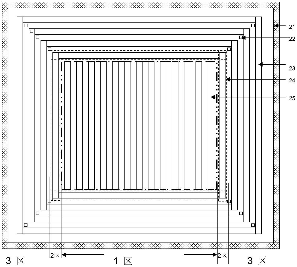
[0127] Such as figure 1 Shown is a top view of an existing power semiconductor device Figure one . In the top view, the embodiment of the present invention can be divided into zone 1, zone 2, and zone 3. Zone 1 is the current flow zone in the middle of the power semiconductor device. The current flow zone includes alternately arranged P-type regions 25 and N-type regions. The P-type region 25 is also the P-type region formed in the current flow region. The N-type thin layer, the N-type region is also the N-type thin layer formed in the current flow region; in the current flow region, the current will pass through the N-type region from the source to the drain through the channel, and the The P-type region 25 and the N-type region form a depletion region to withstand voltage in the reverse blocking state. Zone 2 and Zone 3 are the terminal protection structure area of ​​the power semiconductor device. When the device is turned on, the terminal protection structure does not pro...


PUM


Abstract

The invention discloses a power semiconductor device. The drift region is composed of a super junction drift region and a single drift region, so that the device of the present invention can realize the parallel connection of a super junction device and a single drift region device. The super junction drift region is composed of multiple alternating Arranged N-type thin layer and P-type thin layer, the single drift region is composed of N-type doped first N-type layer; the specific on-resistance of the device can be optimized by using the super junction drift region to obtain low specific conduction resistance; using the soft reverse recovery characteristics of the device in the turn-off process of the single drift region, the reverse recovery characteristics of the device in the turn-off process can be softened, and the reverse recovery characteristics and impact resistance of the device can be improved. Reduce recovery current shock. The invention discloses a method for manufacturing a power semiconductor device.

Description

Technical field [0001] The present invention relates to the field of semiconductor integrated circuit manufacturing, in particular to a power semiconductor device; the present invention also relates to a method for manufacturing a power semiconductor device. Background technique [0002] Super junction MOSFET adopts a new withstand voltage layer structure, using a series of alternately arranged P-type semiconductor thin layers and N-type semiconductor thin layers to combine the P-type semiconductor thin layers and N-type semiconductor thin layers at a lower voltage in the off state. Type semiconductor thin layer is depleted to achieve mutual compensation of charges, so that P-type semiconductor thin layer and N-type semiconductor thin layer can achieve high breakdown voltage at high doping concentration, thereby achieving low on-resistance and high breakdown at the same time Voltage, breaking the theoretical limit of traditional power MOSFET. In the US patent US5216275, the abov...

Claims


Application Information

Patent Timeline
Patent Type & Authority Patents(China)
IPC IPC(8): H01L29/739H01L29/06H01L21/331
Inventor 肖胜安雷海波
Owner SHANGHAI HUAHONG GRACE SEMICON MFG CORP
Why Eureka
Try Eureka