
Cord cutting terminal connection structure of stator, motor stator with cord cutting terminal connection structure, and connection method

A technology of terminal connection and stator, which is applied in the field of electric motor stator and connection, and the connection structure of wire-cutting terminals of the stator, which can solve the problems of affecting product production efficiency, affecting service life, cumbersome operation, etc. The effect of avoiding cumbersome operations

Active Publication Date: 2015-05-27
泰兴星德胜电机有限公司
View PDF7 Cites 4 Cited by
  • Summary
  • Abstract
  • Description
  • Claims
  • Application Information

AI Technical Summary

Problems solved by technology

Although this method can solve the above-mentioned problems to a certain extent, first of all, because the processes of connecting copper wires and welding are cumbersome in operation, it will directly affect the production efficiency of the overall product; secondly, the joints of aluminum wires Exposure to the air for a long time is also prone to a series of phenomena such as oxidation, poor contact and fracture, which will affect its service life; finally, because welding and other processes need to pay attention to controlling factors such as time and temperature, its quality control is also more troublesome and difficult. difficulty

Method used


Image

  • Cord cutting terminal connection structure of stator, motor stator with cord cutting terminal connection structure, and connection method
  • Cord cutting terminal connection structure of stator, motor stator with cord cutting terminal connection structure, and connection method
  • Cord cutting terminal connection structure of stator, motor stator with cord cutting terminal connection structure, and connection method

Examples


Embodiment Construction

[0025] Preferred embodiments of the present invention will be described in detail below in conjunction with the accompanying drawings.

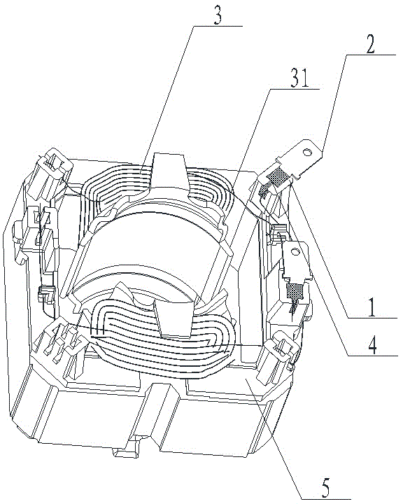
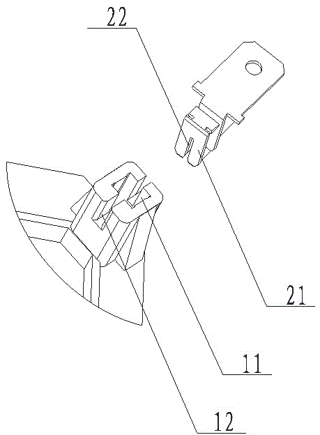
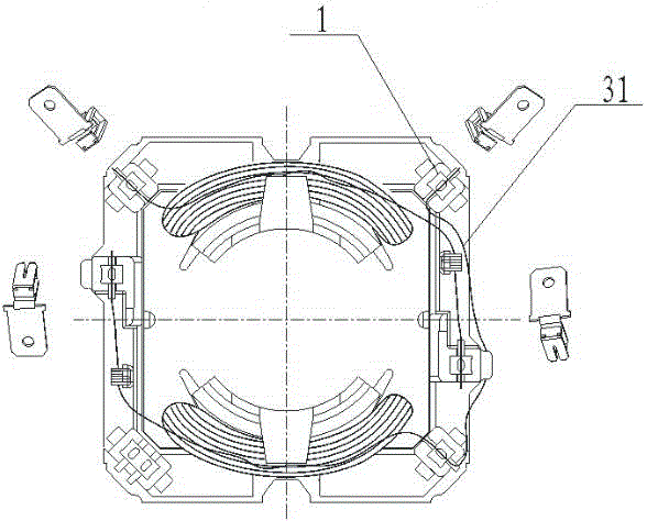
[0026] Such as Figure 1-3 As shown, in the first embodiment of the connection structure of the wire-cutting terminal of the stator of the present invention, it includes: a terminal chamber 1, which has a terminal groove 11 and a wire groove 12 communicating with each other; a terminal 2, which has a connecting part 21 , the connecting part 21 is provided with a second wire groove 22, the connecting part 21 is inserted into the terminal groove 11, and is fixedly connected with the terminal chamber 1, and the second wire groove 22 is set facing the wire groove 12; the joint part 31 of the aluminum wire 3 is arranged in the wire groove 12 and the second wire groove 22; the fixing layer 4 is arranged between the terminal cavity 1, the terminal 2 and the joint part 31. This wire-cutter terminal connection structure fixes the joint part 31 of the...


PUM


Abstract

The invention discloses a cord cutting terminal connection structure of a stator. The cord cutting terminal connection structure comprises a terminal cavity, a terminal, aluminum wires and a fixing layer, wherein a terminal groove and a wire groove which are communicated with each other are formed in the terminal cavity; a connecting part is arranged on the terminal; a second wire groove is formed in the connecting part; the connecting part is inserted into the terminal groove and is fixedly connected with the terminal cavity; the second wire groove faces to the wire groove; the connector parts of the aluminum wires are arranged inside the wire groove and the second wire groove; the fixing layer is arranged among the terminal cavity, the terminal and the connector parts. The invention further discloses a motor stator with the cord cutting terminal connection structure, and a cord cutting terminal connection method of the stator. Compared with the prior art, the cord cutting terminal connection structure has the advantages of high production efficiency, long service life and convenient quality control.

Description

technical field [0001] The present invention relates to the technical field of motor stators, in particular to a stator terminal connection structure, a motor stator including the same and a connection method. Background technique [0002] The stator is the static part of the motor. It is generally composed of three parts: the stator core, the stator winding and the machine base. Its main function is to generate a rotating magnetic field. [0003] In consideration of the cost, more than 70% of the currently used stator windings are made of aluminum wires, which brings some problems to the production and processing. Because the aluminum wire is relatively soft, it is not only easy to break but also prone to oxidation when connecting the terminals. In order to prevent these problems, the currently commonly used method is to connect a section of copper wire to the joint of the aluminum wire and then weld it. to the terminal. Although this method can solve the above-mentioned ...

Claims


Application Information

Patent Timeline
IPC IPC(8): H02K5/22H02K3/50H02K15/12
CPCH02K3/50H02K15/12
Inventor 朱云舫
Owner 泰兴星德胜电机有限公司
Learn More