
Friction wheel transmission type ridge crushing box

A friction wheel drive, friction wheel technology, applied in the application, farming machinery, agricultural machinery and machinery and other directions, can solve the problems of poor interchangeability, difficult processing of gears, worm gears, and difficult assembly and maintenance, and meet the lubrication requirements. Low, easy to assemble and maintain, easy to process

Inactive Publication Date: 2015-06-03
GUANGXI WUFENG MACHINERY CO LTD
View PDF9 Cites 0 Cited by
  • Summary
  • Abstract
  • Description
  • Claims
  • Application Information

AI Technical Summary

Problems solved by technology

Since the transmission box is driven by internal gears or worm gears, the processing of gears and worm gears is difficult, the interchangeability is poor, and the assembly and maintenance of internal parts are difficult, and internal gears or worm gears generally need to be lubricated. Lubrication, which puts forward higher requirements on the sealing of the box

Method used


Image

  • Friction wheel transmission type ridge crushing box
  • Friction wheel transmission type ridge crushing box

Examples


Embodiment 1

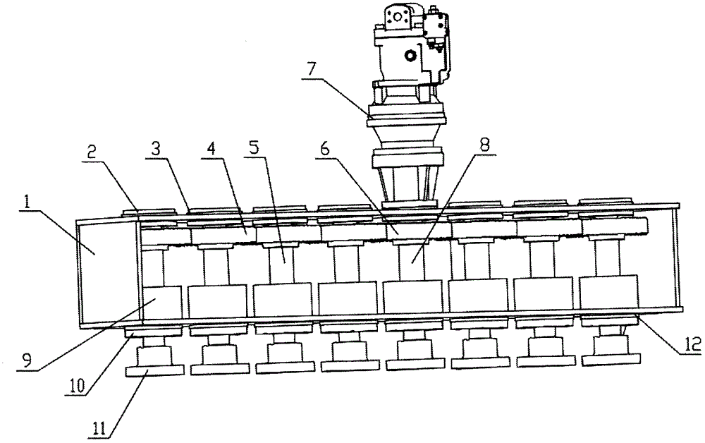
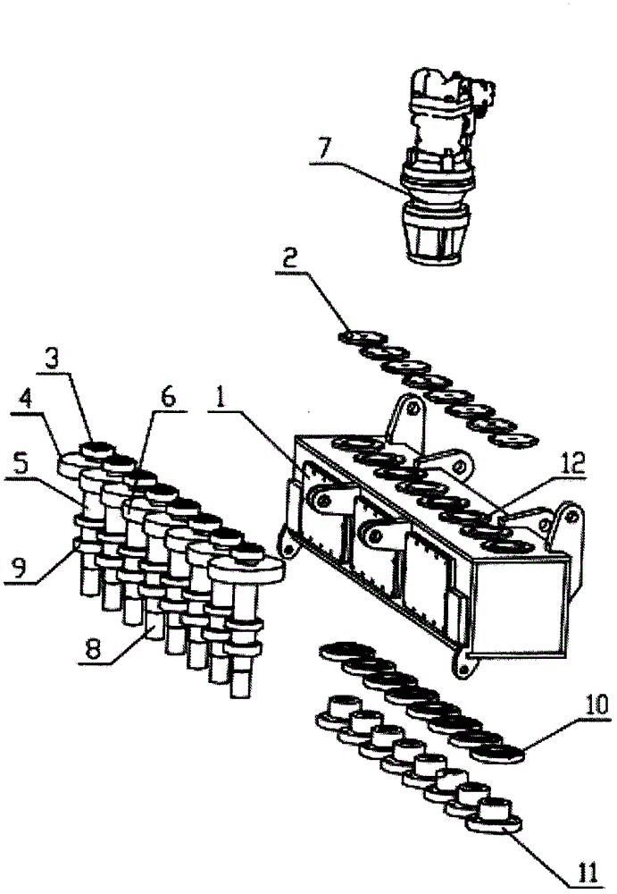
[0021] refer to figure 1 , figure 2 As shown, a friction wheel transmission powder ridge box includes friction wheels, bearing caps 2, 10, shafts, bearings 3, 9, a casing 1 provided with a bearing seat 12, and a coupling 11. The friction wheels include active Friction wheel 6, driven friction wheel 4, the shaft includes a driving shaft 8, a driven shaft 5, the driving friction wheel 6 is fixedly connected with the power source 7, the shaft and the friction wheel are fixedly connected with the same axis, supported by bearings Fixed on the bearing seat 12 provided on the box body 1, the bearing caps 2, 10 are connected with the bearing seat 12 provided on the box body 1 through fasteners, and the adjacent friction wheels are pressed against each other. The coupling 11 Connect with auger bit. When the power source 7 drives the driving friction wheel 6 and the driving shaft 8 to rotate, the corresponding driven friction wheel 4 is driven to rotate through the friction wheel tra...

Embodiment 2

[0026] The difference from Embodiment 1 is that in this embodiment, the driven friction wheel 4 can be set to have different diameters as required, and the power can be distributed to different driven shafts 5 according to the required speed and torque. As the driven friction wheel 4 with a larger diameter than the active friction wheel 6, it will obtain a smaller rotating speed and a larger torque than the active friction wheel 6; otherwise, it will obtain a larger rotating speed and a smaller torque than the active friction wheel 6 .

Embodiment 3

[0028] The difference from Embodiment 1 is that in this embodiment, the two adjacent friction wheels drive the auger bit to rotate in opposite directions, and the auger bit is correspondingly provided with opposite helical blades according to the direction of rotation. In this way, the two adjacent auger bits rotate and cooperate with each other, which can further improve the effect of deep plowing and deep loosening of the auger bits.


PUM


Abstract

The invention discloses a friction wheel transmission type ridge crushing box, which comprises friction wheels, a bearing cover, a shaft, a bearing, a box body with a bearing seat, and a coupling, wherein the friction wheels comprise a driving friction wheel and a driven friction wheel, the driving friction wheel is fixedly connected with the power source, the shaft and the friction wheels are coaxially and fixedly connected, and are fixedly arranged on the bearing seat of the box body through bearing support, the bearing cover is connected with the bearing seat through a fastener, the adjacent friction wheels are mutually pressed, and the coupling is coupled with a spiral drill bit. The friction wheel transmission type ridge crushing box has the advantages that the lubricating requirement is lower, the processing is convenient, the interchangeability is good, and the assembly and maintenance are convenient; the deep tillage and loosening effects are further improved, and more air can exist in soil.

Description

technical field [0001] The invention relates to the field of agricultural tillage machinery, in particular to a friction wheel-driven powder ridge box for multifunctional tillage equipment. Background technique [0002] The main function of farming equipment is to deep plow and subsoil the land. In the past, the deep plow and subsoiler used a tractor as a platform and used old traditions such as plowing, beating, and harrowing. The process was complicated and the efficiency was low. Moreover, it is necessary to work when the cultivated land is moist and soft, the cultivation time is short, and the cultivation depth is shallow, which is not conducive to agricultural production. Therefore, for large areas of land that require deep plowing and deep loosening, the traditional method has been unable to adapt. For this reason, the current automated deep plowing and deep loosening have emerged. All types of tillage equipment require the transmission and distribution of power to on...

Claims


Application Information

Patent Timeline
Patent Type & Authority Applications(China)
IPC IPC(8): A01B33/08
Inventor 李阳铭
Owner GUANGXI WUFENG MACHINERY CO LTD
Learn More