Eureka AIR delivers breakthrough ideas for toughest innovation challenges, trusted by R&D personnel around the world.

A method for detecting solder joints and performing soldering on a complete electronic product

A technology for detecting electronic products and solder joints, applied in welding equipment, welding equipment, auxiliary devices, etc., can solve problems that affect the processing efficiency and quality of electronic products, miss solder, repeat solder, etc., and achieve automatic detection and The effect of repair welding operation, increasing accuracy and improving work efficiency

Active Publication Date: 2017-01-18
河北科瑞达仪器科技股份有限公司
View PDF7 Cites 0 Cited by
  • Summary
  • Abstract
  • Description
  • Claims
  • Application Information

AI Technical Summary

Problems solved by technology

[0002] Soldering is a processing method often used in the processing of electronic products. A four-axis automatic soldering machine is used for soldering. After the soldering of the entire electronic product is completed, it is necessary to inspect the soldering points of the entire machine to detect whether there is continuous welding and virtual soldering. Solder points that are soldered or not soldered, the inspection process requires personnel to observe and judge, and the results of observation and inspection often make mistakes, resulting in repeated soldering and missing solder unqualified points, seriously affecting the processing efficiency and quality of electronic products

Method used


Image

  • A method for detecting solder joints and performing soldering on a complete electronic product
  • A method for detecting solder joints and performing soldering on a complete electronic product
  • A method for detecting solder joints and performing soldering on a complete electronic product

Examples


Embodiment Construction

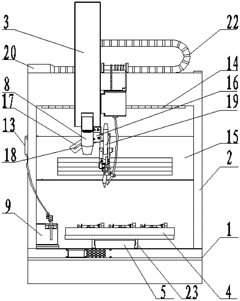
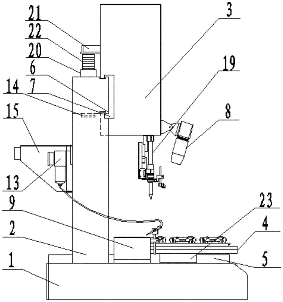
[0020] A method for detecting solder joints and replenishing solder on a complete electronic product, the method is realized by means of an automatic soldering machine with a CPU, wherein the structure of the automatic soldering machine includes a workbench 1, an X-axis, a Y-axis , Z-axis and a four-axis numerical control system composed of a rotation axis around the Z-axis, the welding head is fixed on the Z-axis, and an industrial camera is fixedly arranged on the Z-axis. On this basis, the method includes the following steps:

[0021] A. Collect the image data of the standard complete machine and store it in the data memory of the CPU: fix each component in the complete electronic product on the workbench 1 of the automatic soldering machine, such as figure 1 and figure 2 As shown, the movement of the X-axis guide rail 6, the movement of the Y-axis guide rail 5, the movement of the vertical guide column 3 in the Z-axis direction, and the rotation of the welding torch aroun...


PUM


Abstract

The invention provides a method for detecting soldering points of electronic product complete machines and performing tin soldering on the electronic product complete machines. The method is implemented by the aid of an automatic tin soldering machine with a CPU (central processing unit). The automatic tin soldering machine structurally comprises a workbench, an X-axis, a Y-axis, a Z-axis and a four-axis numerical control system, wherein the four-axis numerical control system is formed around a rotating shaft of the Z-axis. A soldering head is fixed on the Z-axis which is fixedly provided with an industrial camera. The method includes that standard image information of various kinds of qualified electronic product complete machines is stored in a data storage unit of the CPU, the industrial camera acquires an image of a to-be-detected electronic product complete machine, the image is stored in the data storage unit and is transmitted to a data processor, the data processor compares to-be-detected image information with the standard information in the data storage unit, if the image information is identical to the standard information, tin soldering points of the to-be-detected complete machine are qualified, or otherwise, the tin soldering points are unqualified, the data storage unit displays differences of the to-be-detected image on a display screen in a partial enlarged manner, repair soldering is performed, and if the soldering points are still unqualified, manual detection is performed.

Description

technical field [0001] The invention belongs to the technical field of electronic product processing, and in particular relates to a method for detecting solder joints on a complete electronic product and supplementing solder. Background technique [0002] Soldering is a processing method often used in the processing of electronic products. A four-axis automatic soldering machine is used for soldering. After the soldering of the entire electronic product is completed, it is necessary to inspect the soldering points of the entire machine to detect whether there is continuous welding and virtual soldering. Solder joints that are soldered or not soldered, the inspection process requires personnel to observe and judge, and the results of observation and inspection often make mistakes, resulting in repeated soldering and missing solder unqualified points, seriously affecting the processing efficiency and quality of electronic products. Contents of the invention [0003] The inv...

Claims


Application Information

Patent Timeline
Patent Type & Authority Patents(China)
IPC IPC(8): B23K3/00B23K3/08B23K31/12
CPCB23K3/00B23K3/08B23K31/12
Inventor 郝拴菊郝立辉
Owner 河北科瑞达仪器科技股份有限公司
Why Eureka
Eureka Blog
Learn More