Device and method for adjusting zero sensor

A technology of zero position sensor and adjustment device, which is applied in the direction of measuring device, optical device, photo-plate making process exposure device, etc., and can solve the problems of affecting accuracy and complex structure, etc.

Active Publication Date: 2015-06-03
SHANGHAI MICRO ELECTRONICS EQUIP (GRP) CO LTD
View PDF5 Cites 5 Cited by
  • Summary
  • Abstract
  • Description
  • Claims
  • Application Information

AI Technical Summary

Problems solved by technology

In this way, there is one more component, which is relatively complex in structure, and one more error item affects the accuracy, and also causes a series of problems in manufacturing, assembly, cost, etc., see figure 1
[0007] Again, in order to accommodate the downward extension structure of the adjustment plate, and to leave enough space for adjustment, the base block must open a hole large enough to serve as a main load-bearing member. The existence of this large hole near the fixing screw is very important The overall stress before and after locking and fixing will have a greater negative impact

Method used


Image

  • Device and method for adjusting zero sensor
  • Device and method for adjusting zero sensor
  • Device and method for adjusting zero sensor

Examples


Embodiment Construction

[0035] Specific embodiments of the present invention will be described in detail below in conjunction with the accompanying drawings.

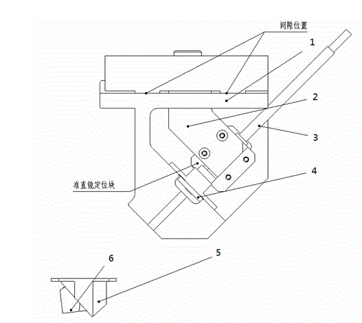
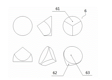
[0036] The shape of the corner mirror 6 is as follows image 3 As shown, it has three light reflecting surfaces with excellent perpendicularity. image 3 Among them, 61 is a light reflecting surface, 62 is a cylindrical surface, and 63 is a large circular end surface. According to this characteristic, the incident light from any direction within the cone angle within an angular range deviated from the cylindrical axis (optical axis) of the retroreflector will be reflected back in parallel.

[0037] like Figure 4 As shown, on the large circular end face 63 of the corner cone reflector 6, when the incident light moves away from the central optical axis of the corner cone reflector, according to the characteristics of the corner cone reflector, the reflected light will also move away from the center optical axis of the corner cone reflector T...


PUM


Abstract

The invention discloses a zero sensor, which comprises a base, an adjusting plate, a laser collimating mirror, a corner cube reflecting mirror, and a position sensor, wherein the base is used for positioning, supporting and containing the zero sensor, the adjusting plate comprises a first positioning pin, and can be slide at one surface of the base, a first positioning hole and a locking device are arranged on the adjusting plate, the locking device is used for locking the corresponding positions of the adjusting plate and the base, the laser collimating mirror is used for reflecting laser, and is arranged on the base, the corner cube reflecting mirror is provided with three mutually vertical light reflecting surfaces and a large circular end surface, and is used for receiving and transmitting the incident light of the laser collimating mirror, the position sensor is used for receiving the reflecting light of the laser, the reflecting light forms a reflecting light spot on the position sensor, the position sensor is arranged on the base, and the positions of the position sensor and the laser collimating mirror are relatively fixed.

Description

technical field [0001] The invention relates to the field of integrated circuit equipment manufacturing, in particular to a zero-position sensor adjustment device and method. Background technique [0002] The laser interferometer system is used in the position measurement system of the lithography machine. Since the laser interferometer is an incremental measurement system that can only provide accurate measurement of relative displacement, it is necessary to use a zero position sensor to provide a position for the laser interferometer as an initial zero point. [0003] In the patent application number CN201010530550.6, a structure of a two-degree-of-freedom zero position sensor is disclosed. The PSD (two-dimensional planar photoelectric position sensor) is fixed on the base, and the laser collimator is fixed inside the base. structure on the adjustment plate. like figure 1 as shown in, figure 1 It includes a base 1, an adjustment plate 2, a laser collimating mirror...

Claims


Application Information

Patent Timeline
IPC IPC(8): G01B11/00G03F7/20
Inventor 王凯
Owner SHANGHAI MICRO ELECTRONICS EQUIP (GRP) CO LTD
Why Eureka
Try Eureka