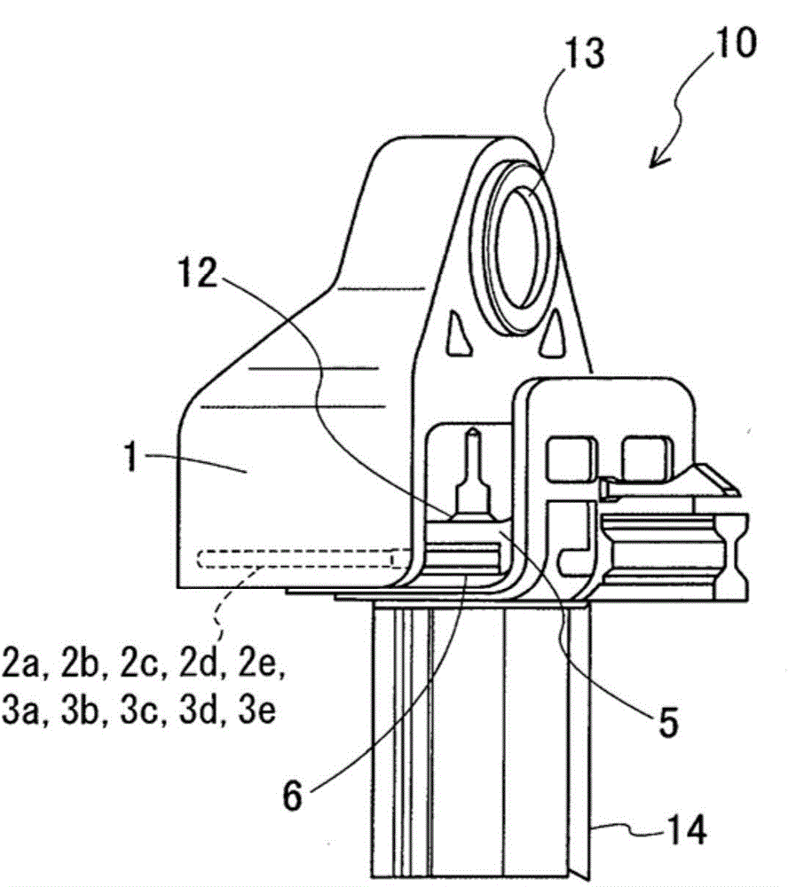

Fitted housing

A technology for shells and assembly parts, which is applied in the direction of measuring device shells, measuring devices, household components, etc., and can solve problems such as damage to contact areas

Inactive Publication Date: 2015-06-03
DENSO CORP
View PDF6 Cites 0 Cited by
  • Summary
  • Abstract
  • Description
  • Claims
  • Application Information

AI Technical Summary

Problems solved by technology

[0004] However, the above-mentioned conventional technology has the following problems: the smooth fitting between the container and the housing is inhibited due to the self-compressing mechanism; the contact between the self-compressing mechanism itself or the container or the housing and the self-compressing mechanism at the time of fitting damage to the area; and no self-compression force is applied in the case of a large amount of resin melting at the time of laser welding

Method used


Image

  • Fitted housing
  • Fitted housing
  • Fitted housing

Examples


no. 1 approach

[0031] will refer to Figure 2 to Figure 4 The first embodiment will be described.

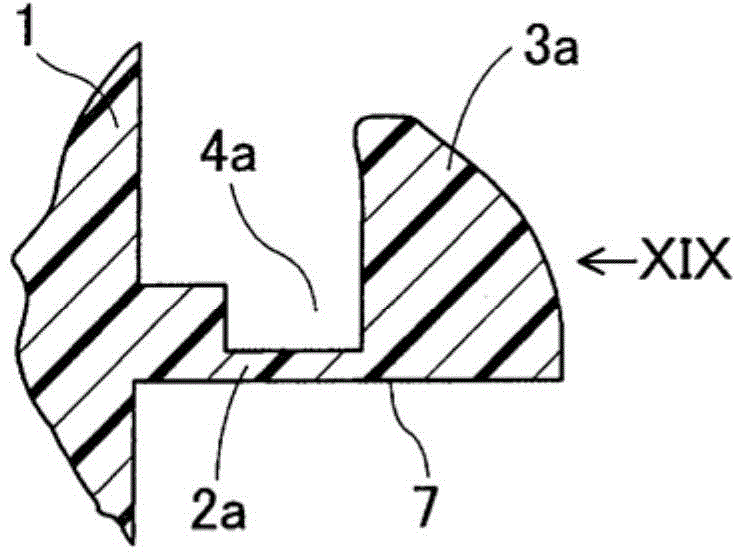
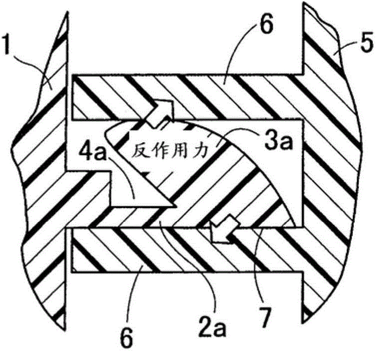
[0032] Such as figure 2 As shown in , the first housing 1 made of synthetic resin or the like includes a rib 2 a protruding from one surface of the housing 1 . The material of the rib 2a is thermoplastic synthetic resin. One side surface of the rib 2 a is a flat contact surface 7 . On the other side surface of the rib 2a, a snap piece 3a made of thermoplastic resin and having a tongue-shaped cross section is provided so as to protrude from the distal end portion of the rib 2a. The snap piece 3 a generates elastic force in a direction perpendicular to the contact surface 7 . On the other side surface of the rib 2a is formed a movable area 4a adjacent to the snap piece 3a and is a U-shaped groove. The movable area 4 a is a space in which the catch 3 a is accommodated when the catch 3 a is elastically displaced toward the first housing 1 and the rib 2 a and contracts in a direction perpendi...

no. 2 approach

[0039] will refer to Figure 5 to Figure 7 A second embodiment will be described. Since matters related to press-fitting and welding in the second embodiment and subsequent embodiments are similar to those in the first embodiment, description thereof will be omitted, and the second embodiment and The description of the following embodiments is limited to the description of the ribs, snaps and movable regions provided for the first housing.

[0040] Such as Figure 5 to Figure 7 As shown, the first housing 1 made of synthetic resin or the like includes a rib 2 b protruding from one surface of the first housing 1 . The material of the ribs 2b is thermoplastic synthetic resin. One side surface of the rib 2 b is a flat contact surface 7 . On the other side surface of the rib 2b, a catch 3b made of thermoplastic resin and having a tongue-shaped cross section is provided so as to protrude from the distal end portion of the rib 2b and be inclined toward the first housing 1 . The...

no. 3 approach

[0042] Such as Figure 8 to Figure 10 As shown, the first housing 1 made of synthetic resin or the like includes a rib 2 c protruding from one surface of the first housing 1 . The material of the rib 2c is thermoplastic synthetic resin. One side surface of the rib 2 c is a flat contact surface 7 . A snap piece 3c made of thermoplastic resin and having a herringbone-shaped cross section is provided to protrude from the other side surface of the rib 2c. The snap piece 3 c generates elastic force in a direction perpendicular to the contact surface 7 . In addition, a movable area 4c having a tunnel shape is formed in the snap piece 3c. The movable region 4c is a space that accommodates the catch 3c and is thereby compressed when the catch 3c is pressed from its apex toward the rib 2c and elastically displaced to contract. Although not shown, a taper is formed at one or both ends of the catch 3c so that the height of the apex of the catch 3c from the contact surface 7 gradually...


PUM


Abstract

A fitted housing includes a first housing and a second housing. The first housing includes a rib projecting from its one surface. The rib includes a flat contact surface on one side surface of the rib, and includes a snap piece that generates elastic force in a direction perpendicular to the contact surface and a movable region that accommodates the snap piece, which is contracted, on the other side surface of the rib. The second housing is fitted to the first housing and includes a rail having an inside distance corresponding to a distance between a vertex of the contracted snap piece and the contact surface. The rib and the snap piece are fitted to the rail. A fitted portion between the first housing and the second housing is welded.

Description

technical field [0001] The present disclosure relates to a fitting housing including a self-tightening mechanism as a fitting portion. Background technique [0002] Many techniques have been proposed by which two housings made of thermoplastic resin are integrated by welding them together. For example, one of the techniques described in JP-A-2008-207358 is a welding method by which a self-pressing holding mechanism is provided so that the welded portion can be fixed without previously fixing the welded portion by an external pressing mechanism. Laser welding is performed without the need for a container, and the container can be sealed quickly and reliably, even for relatively thick components. [0003] The technique described in JP-A-2008-207358 is a method of welding together a member A having a layer (a) and a member B having a layer (b), the layer (a) made of a thermoplastic resin exposed to the member On at least a part of the outer surface of A, the layer (b) made of...

Claims


Application Information

Patent Timeline
IPC IPC(8): G01D11/24
CPCB29C65/06B29C65/08B29C65/1635B29C65/565B29C65/58B29C65/72B29C66/12449B29C66/54B29L2031/3481F16B17/008G01P15/0891Y10T403/5793
Inventor 小原侑也藤原功一
Owner DENSO CORP
Learn More