Infrared thermal imaging low-temperature economizer leakage detection device

A low-temperature economizer and infrared thermal imaging technology, applied in the application of light to test fluid tightness, etc., can solve the problems of long leak detection cycle and inaccurate positioning, and achieve the effects of sensitive response, precise positioning, and simple device structure

Inactive Publication Date: 2015-06-03
CHINA JILIANG UNIV
View PDF10 Cites 6 Cited by
  • Summary
  • Abstract
  • Description
  • Claims
  • Application Information

AI Technical Summary

Problems solved by technology

The disadvantage of this method is that it needs to stop some economizers for trou

Method used


Image

  • Infrared thermal imaging low-temperature economizer leakage detection device
  • Infrared thermal imaging low-temperature economizer leakage detection device
  • Infrared thermal imaging low-temperature economizer leakage detection device

Examples


Embodiment Construction

[0028] The present invention will be further described below in conjunction with the accompanying drawings and embodiments.

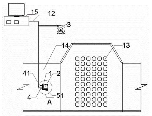
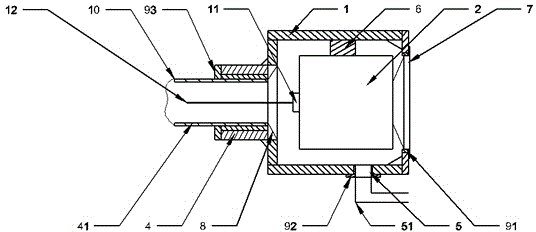
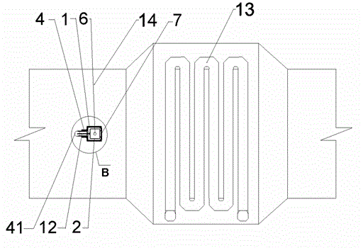
[0029] Such as Figure 1 to Figure 4 As shown, the infrared thermal imaging low-temperature economizer leak detection device of the present invention includes a housing 1 and an infrared thermal imager 2 . Wherein, the casing 1 is provided with an air inlet 4 and an air outlet 5; the infrared thermal imager 2 is fixedly installed in the cavity of the casing 1 through a fastener 6, and a through hole is opened on the wall of the casing 1, and the infrared thermal imager The lens 7 of 2 is installed in this through hole.

[0030] As a preferred embodiment, the present invention also includes a cooling fan 3 placed outside the flue 14 . Such as figure 1 , 2 , 4, the cooling fan 3 is connected to one end of the air inlet duct 41, and the other end of the air inlet duct 41 is connected to the air inlet 4 of the housing 1 after passing through the flue 14...


PUM


Abstract

The invention discloses an infrared thermal imaging low-temperature economizer leakage detection device, which comprises a shell and an infrared thermal imaging instrument, wherein the shell is provided with an air inlet and an air outlet; the wall of the shell is provided with a through hole; the infrared thermal imaging instrument is installed in the cavity of the shell; the lens of the infrared thermal imaging instrument is installed in the through hole. According to the infrared thermal imaging low-temperature economizer leakage detection device, the leakage position of the low-temperature economizer can be accurately positioned, and the infrared thermal imaging low-temperature economizer leakage detection device has the advantages of sensitivity in reaction, low cost, simple structure and the like and can be applied to leakage detection in power station boilers and industrial boilers.

Description

technical field [0001] The invention relates to a leak detection device for a low-temperature economizer of a boiler, in particular to a device for detecting leaks of a low-temperature economizer by using an infrared thermal imager. Background technique [0002] In thermal power plants, among the various losses that affect boiler efficiency, the heat loss of boiler exhaust smoke accounts for the largest proportion. In general, for every 10°C increase in the exhaust gas temperature, the heat loss of the exhaust gas will increase by 0.5%~0.8%, and the corresponding increase in coal consumption will be 1.2%~2.4%. Taking a subcritical boiler with a calorific value of 20,000kJ / kg and a capacity of 1,000 t / h as an example, it will consume several thousand tons of power coal per year, so reducing the exhaust gas temperature has important practical significance for boiler efficiency . In order to reduce the exhaust gas temperature, reduce the heat loss of the exhaust gas, and impr...

Claims


Application Information

Patent Timeline
IPC IPC(8): G01M3/38
Inventor 王进卿姜介炜池作和张光学华隽石薛飞
Owner CHINA JILIANG UNIV
Why Eureka
Try Eureka