Batch determinator for soil saturated water conductivity of automatic flow-control constant head with float ball and lever
A hydraulic conductivity and measuring instrument technology, which is applied in the field of measuring instruments for measuring soil saturated hydraulic conductivity, can solve the problems of high measurement cost, low measurement efficiency, large error between sample data, etc., and achieve improved measurement accuracy and simple structure , low cost effect
- Summary
- Abstract
- Description
- Claims
- Application Information
AI Technical Summary
Problems solved by technology
Method used
Image
Examples
Embodiment 1
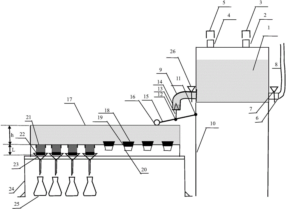
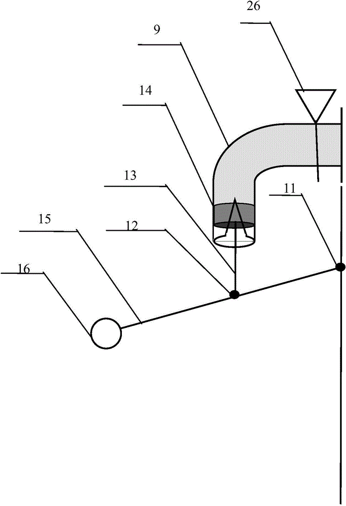
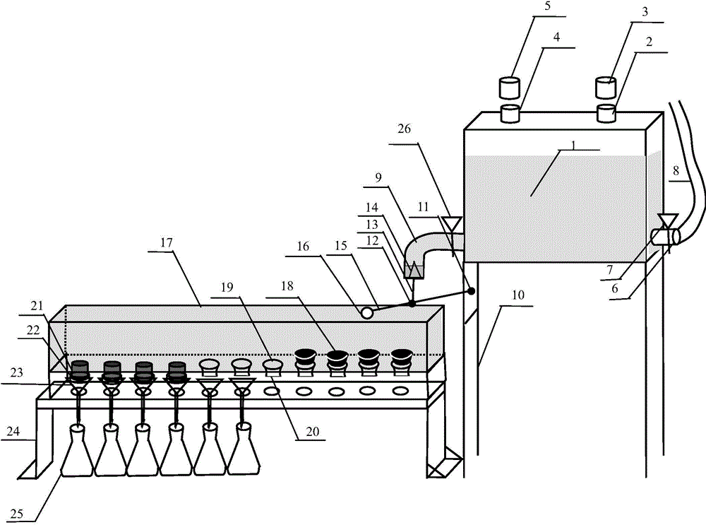
[0037] control figure 1 and figure 2, Batch measuring instrument for soil saturated hydraulic conductivity with automatic water addition and constant water head, which is composed of four parts connected in sequence: water supply device, floating ball lever device, water constant device, and water bearing device. The water supply device includes a water supply tank 1, a water inlet 2, a water inlet screw cap 3, an exhaust port 4, an exhaust port screw cap 5, an air inlet 6, an air inlet valve 7, an air inlet conduit 8, and an outlet pipe of the water supply tank 9. Outlet pipe valve 26, water supply tank support 10 and other parts. Float lever device comprises lever 15, first fulcrum 11, second fulcrum 12, float 16, piston 14, parts such as piston connecting rod 13. The water-fixing device is made of parts such as water-fixing tank 17, ring knife exposure opening 19, rubber stopper 18, rubber sheath 20, ring knife 21, ring knife bottom cover 22. Water receiving device is m...
Embodiment 2
[0098] Float lever automatic control flow fixed water head soil saturated hydraulic conductivity batch tester, composed of water supply device, float lever device, water constant device and water receiving device; the water supply device includes a water supply tank 1, a water supply tank bracket 10 and a water supply Tank outlet pipe 9, the top of the water supply tank 1 is provided with a plugged water inlet 2 and a plugged exhaust port 4, the water supply tank outlet pipe 9 is located at the bottom of the water supply tank 1, and the water supply box body is at the same level as the water supply tank outlet pipe Air inlet 6 is arranged at the place, and air inlet 6 is provided with air inlet duct 8, and valve is all arranged in water supply tank outlet pipe 9 and air inlet 6, and the end of water supply tank outlet pipe 9 is that the cross-section is narrow at the top and wide at the bottom. The wedge-shaped opening; the floating ball lever device includes a lever 15, a floa...
PUM
 Abstract
Description
Claims
Application Information
 - R&D
- Intellectual Property
- Life Sciences
- Materials
- Tech Scout
- Unparalleled Data Quality
- Higher Quality Content
- 60% Fewer Hallucinations
Browse by: Latest US Patents, China's latest patents, Technical Efficacy Thesaurus, Application Domain, Technology Topic, Popular Technical Reports.
© 2025 PatSnap. All rights reserved.Legal|Privacy policy|Modern Slavery Act Transparency Statement|Sitemap|About US| Contact US: help@patsnap.com


