Porous acoustical holography method for sound field identification

An acoustic holography and sound field technology, applied in the field of porous acoustic holography for sound field recognition, can solve problems such as difficult sound source location and poor resolution of sound field recognition

Active Publication Date: 2015-06-03
TSINGHUA UNIV
View PDF5 Cites 5 Cited by
  • Summary
  • Abstract
  • Description
  • Claims
  • Application Information

AI Technical Summary

Problems solved by technology

However, affected by factors such as processing, installation, and transportation, the aperture of a single microphone array cannot be too large. When the microphone array cannot be close to the

Method used


Image

  • Porous acoustical holography method for sound field identification
  • Porous acoustical holography method for sound field identification
  • Porous acoustical holography method for sound field identification

Examples


Embodiment Construction

[0050] The present invention will be described in detail below in conjunction with the accompanying drawings. However, it should be understood that the accompanying drawings are provided only for better understanding of the present invention, and they should not be construed as limiting the present invention.

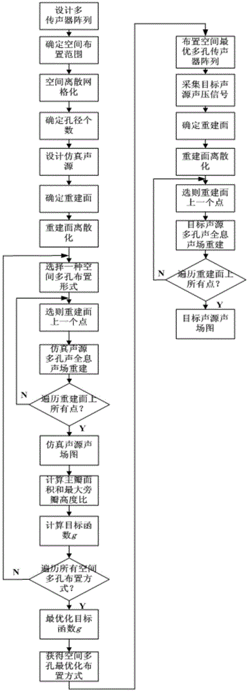
[0051] Such as figure 1 As shown, the porous acoustic holography method for sound field recognition of the present invention comprises the following steps:

[0052] 1. Design and process a single microphone array, and find the optimal layout of the porous microphone array in a limited space through simulation calculations. The specific process is:

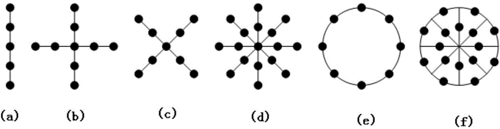
[0053] 1) Design the relevant parameters of each single microphone array according to the processing and installation requirements, wherein, the relevant parameters of each single microphone array include the microphone array aperture D 0 , the number of microphones m and the layout of the microphones.

[0054] Such as ...


PUM


Abstract

The invention relates to a porous acoustical holography method for sound field identification. The porous acoustical holography method comprises the following steps: 1) designing and processing single microphone arrays, and seeking an optimal arrangement form of the porous microphone arrays in a restricted space through simulating calculation; 2) arranging n single microphone arrays in the actual testing space according to the optimal arrangement form of the porous microphone arrays obtained in the step 1); 3) utilizing the spatial porous microphone arrays to acquire sound pressure signals of a target sound source, selecting a sound field reestablishing surface between the target sound source and the porous microphone arrays, performing porous sound holographic sound field reestablishing on the target sound source, and obtaining the sound field pattern of the target sound source, wherein the main lobe center position in the sound field pattern is the estimated position of the target sound source. The porous acoustical holography method disclosed by the invention can be particularly widely applied to noise control of large construction machinery, and automobiles, trains and airplanes moving rapidly.

Description

technical field [0001] The invention relates to the technical field of noise analysis and control, in particular to a porous acoustic holography method for sound field identification. Background technique [0002] In modern society, the problem of noise pollution is becoming more and more serious. Large-scale construction machinery, as well as high-speed moving cars, trains, planes, etc., all bring serious noise troubles to nearby residents. To control noise in a targeted manner, it is first necessary to accurately identify and locate the noise source and sound field. [0003] The far-field acoustic holography method can realize sound field reconstruction and sound source localization, and provide a basis for noise control, so it has been widely used. The traditional acoustic holography method uses a single microphone array, and its sound field recognition resolution increases with the increase of the aperture of the microphone array and the decrease of the measurement dis...

Claims


Application Information

Patent Timeline
IPC IPC(8): G01S5/18
CPCG01S5/18
Inventor 连小珉杨殿阁苗丰王子腾温俊杰
Owner TSINGHUA UNIV
Why Eureka
Try Eureka