Ground gravity unloading support method for large spatial reflector

A technology of gravity unloading and mirror, which is applied in the field of space optics, can solve problems such as the degradation of imaging quality of space optical remote sensors and the decrease of surface shape accuracy of mirrors, and achieve the best engineering implementability effect

Inactive Publication Date: 2015-06-03
CHANGCHUN INST OF OPTICS FINE MECHANICS & PHYSICS CHINESE ACAD OF SCI
View PDF4 Cites 17 Cited by
  • Summary
  • Abstract
  • Description
  • Claims
  • Application Information

AI Technical Summary

Problems solved by technology

[0005] The present invention aims to solve the problem that when a large-scale space reflector enters from the gravitational environment during ground processing and assembly into the microgravity environment during space work, the changes in the two gravity environments will cause the surface shape accuracy of the reflector to decrease, so that the space optical remote sensor can be imaged. To solve the problem of quality degradation, a ground gravity unloading support method for large space mirrors that can actively support the space mirror components during the entire process of space optical remote sensor development is proposed

Method used


Image

  • Ground gravity unloading support method for large spatial reflector
  • Ground gravity unloading support method for large spatial reflector
  • Ground gravity unloading support method for large spatial reflector

Examples


Embodiment

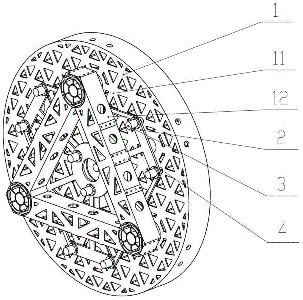
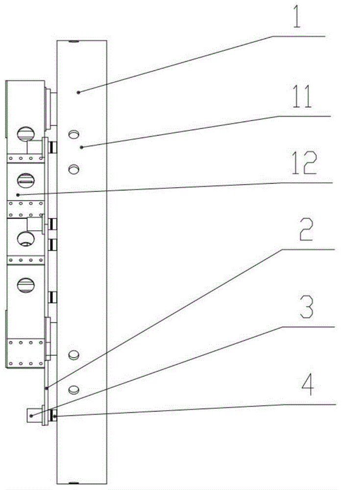
[0027] for a The gravity unloading method of the disk-shaped large-scale space mirror assembly 1 with a diameter of 1.4 m, a mirror thickness ratio of 1:9, and a lightweight ratio better than 70% is implemented as follows:

[0028] Step 1, use finite element analysis software to carry out finite element modeling on the space mirror assembly 1, and analyze the variation of the surface shape accuracy of the space mirror assembly 1 caused by gravity when the space mirror assembly 1 is placed horizontally.

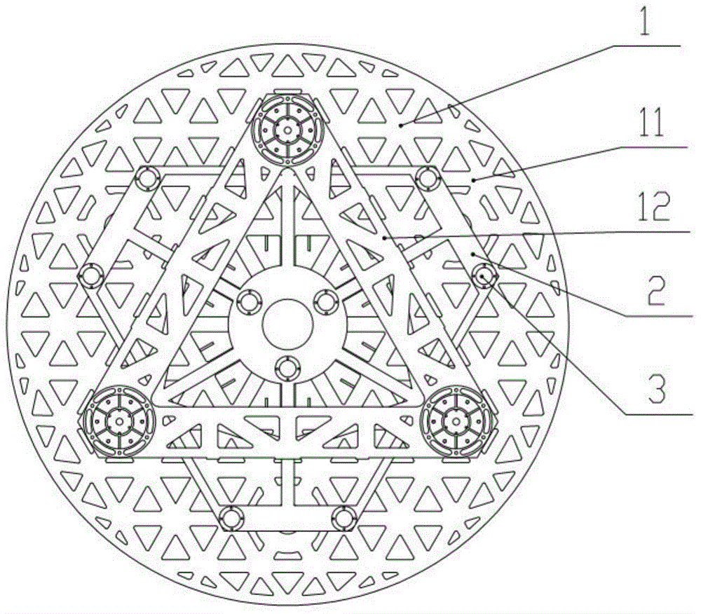
[0029] Step 2, according to the analysis results, it is determined to adopt the active support layout on the back of the space reflector 11 with 6 active support points distributed around the outer circle and 3 active support points distributed around the inner circle, as shown in image 3 shown.

[0030] Step 3, in the finite element software, apply a support force to the active support points on the back of the space mirror 11, and after multiple rounds of iterative calcul...


PUM


Abstract

A ground gravity unloading support method for a large spatial reflector belongs to the technical field of space optics. In order to solve the problem that the gravity environmental variation of the large spatial reflector results in the decline of the surface shape precision of the reflector, a finite element analysis software is adopted to carry out finite element modeling on a spatial reflector assembly and analyze the variation of the reflector surface shape precision caused by gravity when the spatial reflector assembly is horizontally placed; the number and distribution of active support points at the back of the spatial reflector are primarily determined according to the size of the spatial reflector, the variation analysis result of the reflector surface shape precision and the layout condition of a support structure; after support force is applied on the active support points of the spatial reflector, the variation condition of the reflector surface shape precision caused by gravity when the spatial reflector assembly is horizontally placed is analyzed, the reflector surface shape precision result of the spatial reflector assembly is enabled to meet optical design requirements through analyzing and adjusting the size of the support force applied on the active support points and the number and distribution of the active support points, and the gravity unloading of the reflector is realized.

Description

technical field [0001] The invention relates to a ground gravity unloading and supporting method for a large space reflector, which belongs to the field of space optics technology. Background technique [0002] Space optical remote sensors operate in the microgravity environment of space, while the processing, testing and assembly of the space mirror components are all carried out in the gravity environment on the ground. Different gravitational environments change the stress of the space mirror assembly, which in turn causes the space mirror to deform, resulting in a decrease in the surface shape accuracy of the mirror and a decrease in the imaging quality of the space optical remote sensor. Therefore, in the design of the space mirror assembly, it is necessary to reduce the influence of gravity on the surface shape accuracy of the space mirror as much as possible to ensure the imaging quality of the space optical remote sensor. [0003] At present, the space mirror assemb...

Claims


Application Information

Patent Timeline
Patent Type & Authority Applications(China)
IPC IPC(8): G02B7/182G02B7/185G02B7/198
CPCG02B7/182G02B7/185G02B7/198
Inventor 鲍赫李志来张学军杨利伟柴方茂杨会生
Owner CHANGCHUN INST OF OPTICS FINE MECHANICS & PHYSICS CHINESE ACAD OF SCI
Why Eureka
Try Eureka