Fingerprint direction field calculation method based on improved partial differential model

A calculation method and technology of direction field, applied in the fields of automatic fingerprint recognition and digital image processing, can solve the problems of inaccurate direction field, difficulty in distinguishing fingerprint singular points and noise, and difficulty in calculation, so as to reduce the number of iterations, improve the efficiency of the algorithm, Calculate the exact effect

Active Publication Date: 2015-06-03
邳州市鑫盛创业投资有限公司
View PDF3 Cites 7 Cited by
  • Summary
  • Abstract
  • Description
  • Claims
  • Application Information

AI Technical Summary

Problems solved by technology

The gradient-based method is the most extensive and basic method for the fingerprint direction field. It is mainly divided into two parts: the calculation of the point gradient vector and the block gradient vector; however, the simple use of the gradient method cannot effectively anti-noise, especially In the large noise area, the calculation of the direction field based on the gradient is very difficult, and the calculated direction field is very inaccurate
The filtering-based method has good anti-noise performance, but there are only a limited number of filters, and the calculated direction field is not accurate enough, and this type of method needs to calculate the output of each filter and perform In comparison, the calculation is very heavy and the efficiency is low
The model-based method summarizes the rules and limitations of the fingerprint direction field from a global perspective, and uses this to estimate the direction field of the fingerprint. The calculation of the fingerprint direction field based on a polynomial model is the class

Method used


Image

  • Fingerprint direction field calculation method based on improved partial differential model
  • Fingerprint direction field calculation method based on improved partial differential model
  • Fingerprint direction field calculation method based on improved partial differential model

Examples


Embodiment Construction

[0021] Embodiments of the present invention are described in detail below, examples of which are shown in the drawings, wherein the same or similar reference numerals denote the same or similar elements or elements having the same or similar functions throughout. The embodiments described below by referring to the figures are exemplary only for explaining the present invention and should not be construed as limiting the present invention.

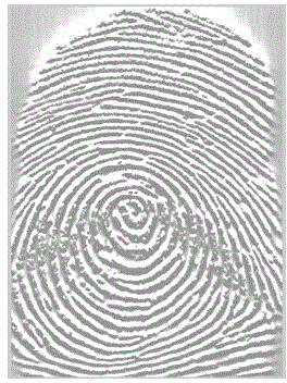
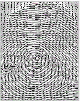
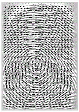
[0022] In the present invention, the fingerprint is preprocessed to distinguish the foreground and background areas of the fingerprint, and the basic gradient algorithm is used in the foreground area to calculate the initial direction field of the fingerprint. Then, by modeling the smoothness and retention of fingerprints, the energy equation is established and solved. In order to avoid the non-smooth defect of the direction field, the initial direction field angle is solved in two parts. In the process of solving the numerical solution obt...


PUM


Abstract

The invention discloses a fingerprint direction field calculation method based on an improved partial differential model, and belongs to the technical field of automatic fingerprint recognition. The fingerprint direction field calculation method mainly comprises two steps: I, solving an initial direction field of fingerprint by using a basic gradient algorithm; II, smoothing the initial direction field by using the improved partial differential model. The fingerprint direction field calculation method mainly aims to improve holding items of a conventional partial differential model, that is, firstly, the situation that the initial direction field in the conventional model is taken as holding standard is improved into the situation that the direction field of previous iteration is taken as the holding standard, and secondly, a static capture singular point function in the conventional model is improved to be a dynamic capture singular point function. By adopting the fingerprint direction field calculation method disclosed by the invention, noise areas and singular point areas can be effectively distinguished, the algorithm is relatively reasonable, the iteration times can be effectively reduced, the algorithm efficiency can be improved, and the direction field can be relatively accurately calculated.

Description

technical field [0001] The invention relates to a fingerprint direction field calculation method based on an improved partial differential model, belonging to the technical fields of automatic fingerprint identification and digital image processing. Background technique [0002] Biometric identification technology is a technology for identification based on each person's unique biological and behavioral characteristics that can be sampled and measured. Because biometric features are not as easy to steal as various certificates, nor are they as easy to forget or crack as passwords and passwords, so they have unique advantages in identification and have been widely studied internationally in recent years. Automated Fingerprint Identification System (AFIS) is more and more popular due to its small size, low cost, easy operation and high reliability, and has become one of the most important biometric technologies. [0003] A general automatic fingerprint recognition system incl...

Claims


Application Information

Patent Timeline
IPC IPC(8): G06K9/00G06K9/32
Inventor 梅园李剑
Owner 邳州市鑫盛创业投资有限公司
Why Eureka
Try Eureka