
Delay circuit

A delay circuit and delay pin technology, applied in electrical components, electronic switches, pulse technology, etc., can solve the problems of power chips without delay function and inconvenience

Inactive Publication Date: 2015-06-03
HONG FU JIN PRECISION IND (SHENZHEN) CO LTD +1
View PDF0 Cites 2 Cited by
  • Summary
  • Abstract
  • Description
  • Claims
  • Application Information

AI Technical Summary

Problems solved by technology

Existing power supply chips do not have a delay function. Usually, it is necessary to set up delay circuits for the power supply chips of each group of power supplies or use software to realize the start-up sequence of high-end chips, which is very inconvenient.

Method used


Image

  • Delay circuit
  • Delay circuit

Examples


Embodiment Construction

[0014] Below in conjunction with accompanying drawing and preferred embodiment the present invention is described in further detail:

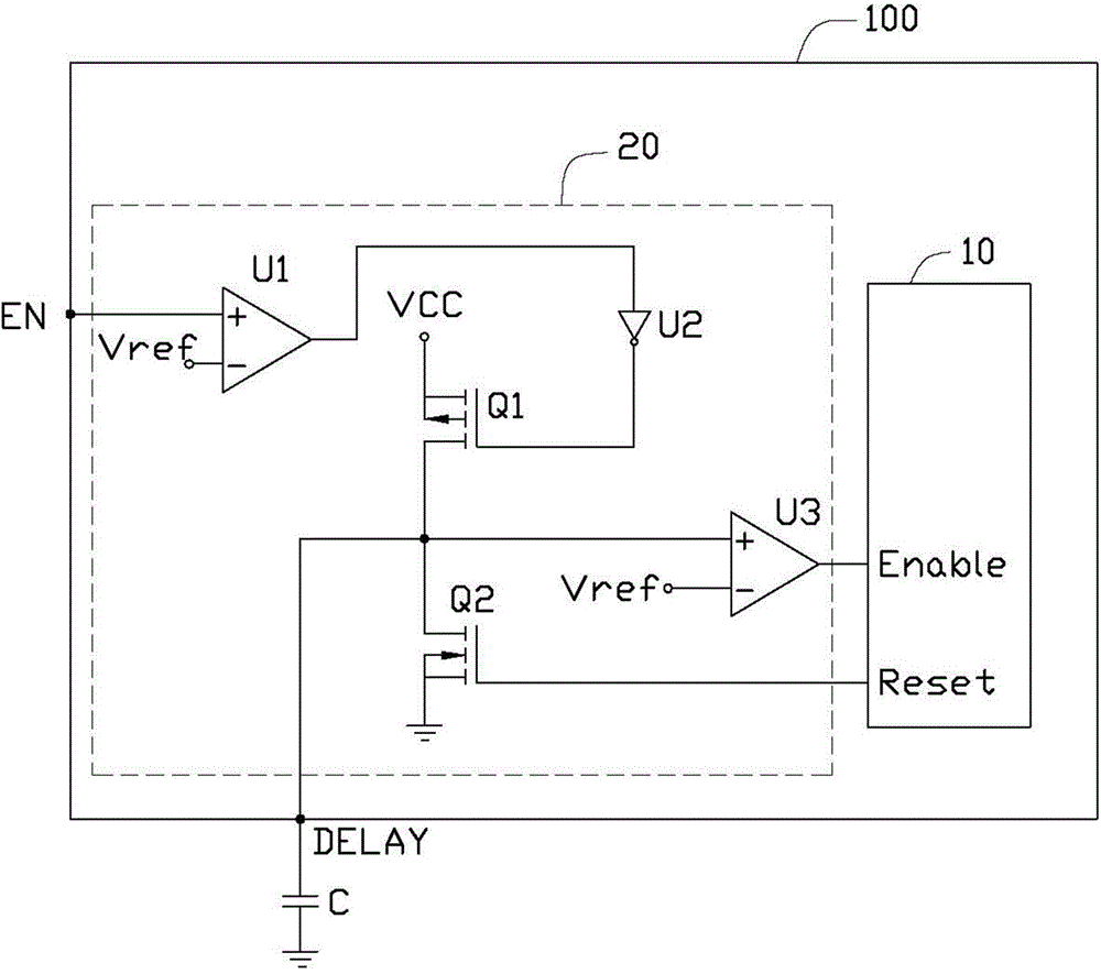
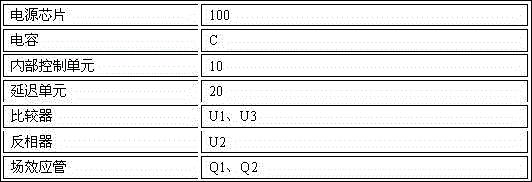
[0015] Please refer to figure 1 A preferred embodiment of the delay circuit of the present invention includes a power chip 100 and a capacitor C, the power chip 100 is provided with an enabling pin EN and a delay pin DELAY, and the delay pin DELAY of the power chip 100 ground through the capacitor C.

[0016] In this embodiment, the power chip 100 includes an internal control unit 10 and a delay unit 20 .

[0017] The internal control unit 10 is provided with an enabling pin Enable and a reset pin Reset. When the enable pin Enable receives a high level signal, the internal control unit 10 starts to work. When the enable pin Enable receives a low level signal, the internal control unit 10 does not work.

[0018] The delay unit 20 includes two comparators U1, U3, two electronic switches (field effect transistors Q1, Q2 in this embodiment) and...


PUM


Abstract

The invention discloses a delay circuit. The delay circuit comprises a capacitor and a power supply chip provided with an enabling pin and a delay pin grounded through the capacitor, wherein the power supply chip comprises an internal control unit and a delay unit; the delay unit is connected between the enabling pin and the delay pin of the power supply chip and an enabling pin of the internal control unit; when the enabling pin of the power supply chip receives a first control signal, the delay unit is used for charging the capacitor connected to the delay pin of the power supply chip; and after the capacitor is charged for a certain period of time, the enabling pin of the internal control unit receives a first enabling signal in order to start working. According to the delay circuit, the startup of the internal control unit in the power supply chip is delayed by using the capacitor connected to the power supply chip.

Description

technical field [0001] The invention relates to a delay circuit. Background technique [0002] High-end chips, such as a central processing unit (CPU), need multiple sets of power supplies to power them. In order for high-end chips to work normally, there are timing requirements when starting up. Existing power chips do not have a delay function. Usually, it is necessary to set up delay circuits for the power chips of each group of power supplies or use software to realize the start-up sequence of high-end chips, which is very inconvenient. Contents of the invention [0003] In view of the above, it is necessary to provide a delay circuit with a delay function without additional settings. [0004] A delay circuit comprising: [0005] a capacitor; and [0006] A power chip provided with an enable pin and a delay pin grounded through the capacitor, comprising: [0007] an internal control unit; and [0008] A delay unit, connected between the enable pin of the power chi...

Claims


Application Information

Patent Timeline
Patent Type & Authority Applications(China)
IPC IPC(8): H03K17/28
Inventor 赖俊安陈群博
Owner HONG FU JIN PRECISION IND (SHENZHEN) CO LTD
Learn More