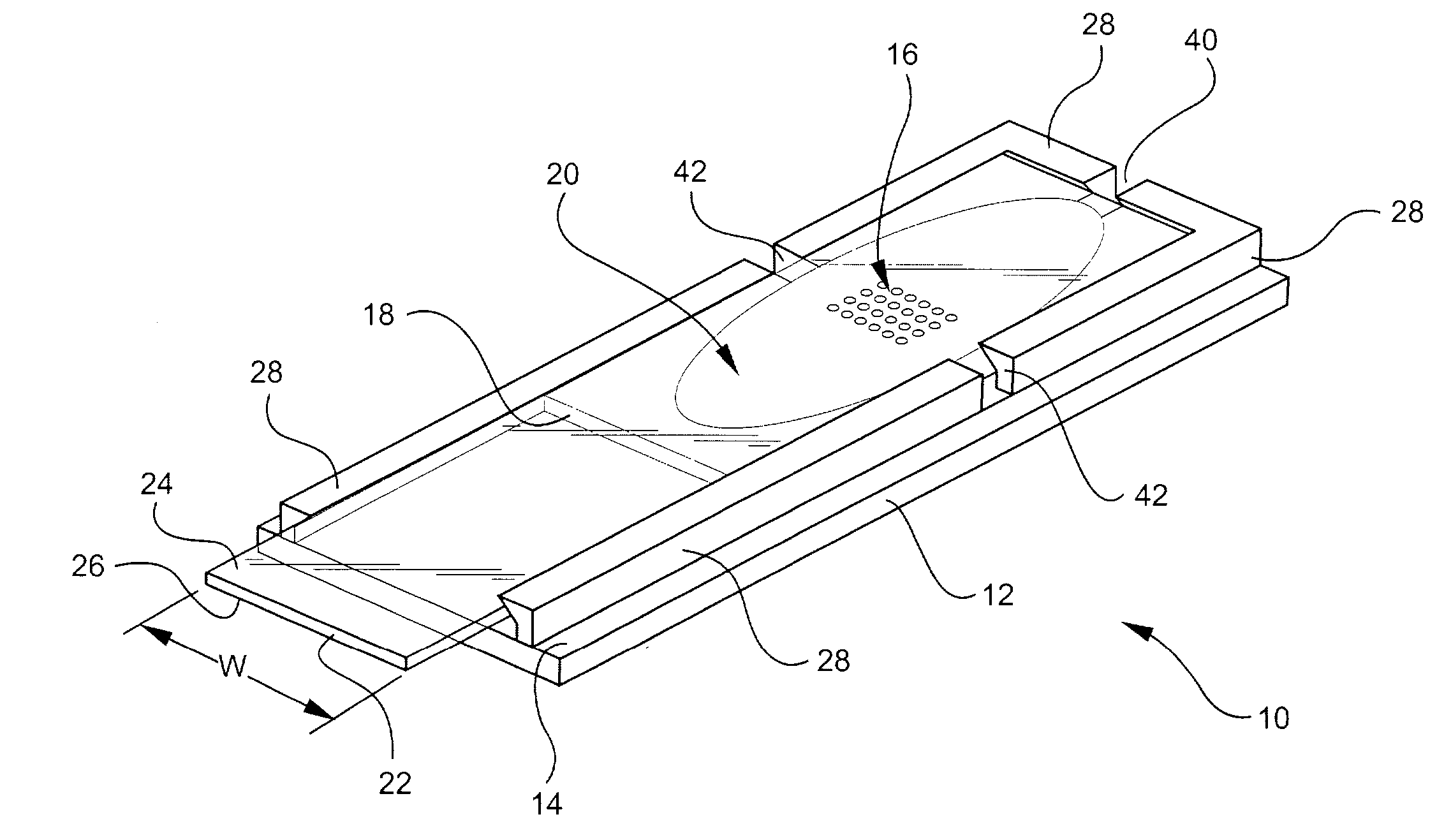
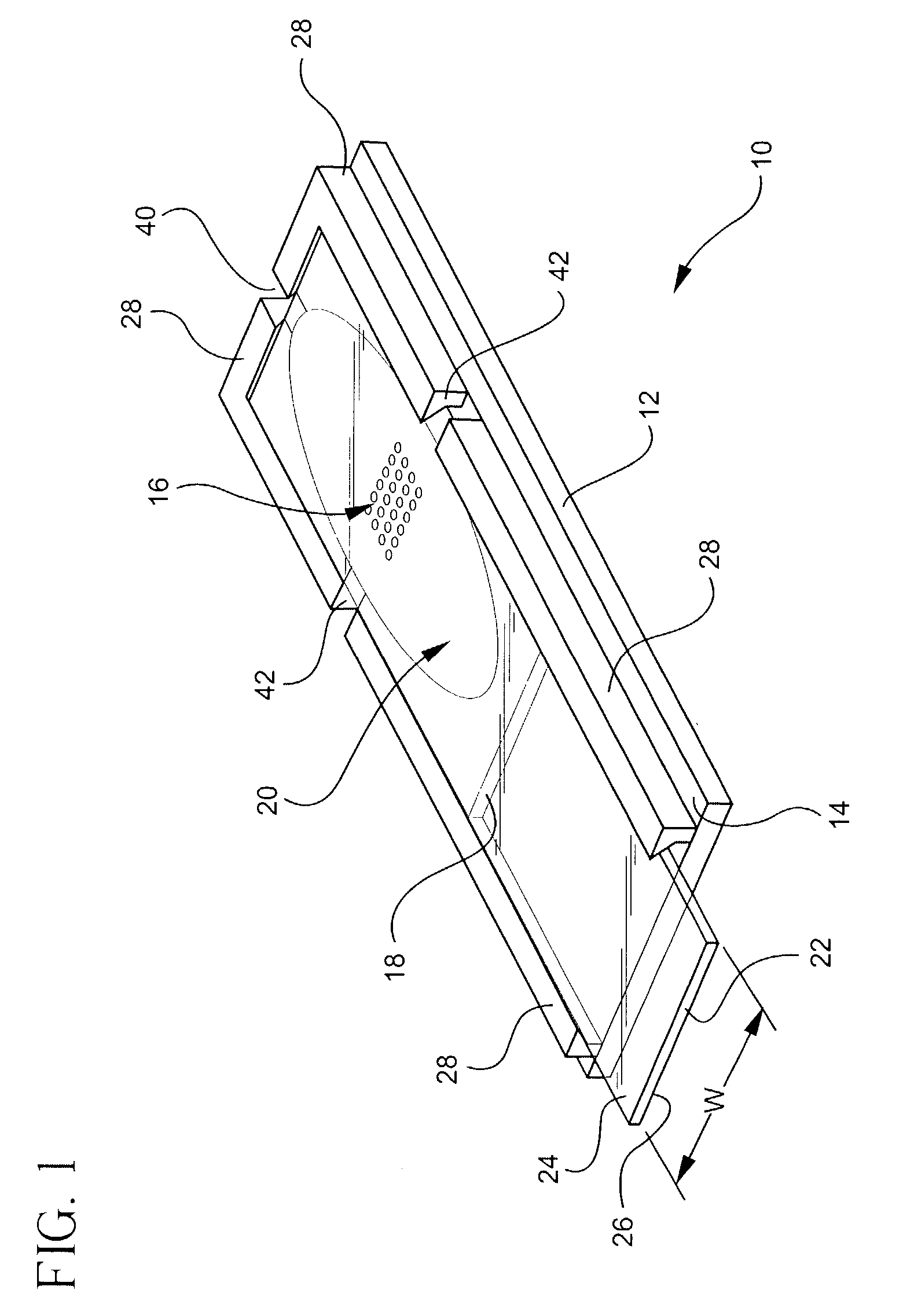
[0006] One embodiment of present invention relates to a biological or
chemical reaction device. Other embodiments relate to methods of forming a biological or
chemical reaction device. The devices and methods include a
reaction chamber formed on a base substrate, a spacer, and a gripping element adapted to receive a cover substrate. According to certain embodiments, the ability to snap-on the cover substrate to the base substrate provides a convenient means of assembling or disassembling different components or modules via a simple
assembly step.
[0020] However, the present invention is not limited to hybridization reactions or any specific type of
hybridization reaction, and the chambers and methods of the various embodiments of the present invention can be used in a wide variety of biological or chemical reactions. Examples of a few of the types of reactions that the present invention can be used, include, but are not limited to fluorescent
in situ hybridization (FISH),
protein array reactions,
immunostaining applications and general
staining or histochemical reactions. In FISH reactions, the analytes in solution include
DNA probes (oligomers, cDNAs, PCR fragments, or clones such as plasmids), BACs (bacterial artificial chromosomes), PACs (phage artificial chromosomes), cosmids, or phage chromosomes, and the surface bound
biomaterial (
analyte binding partner) can include whole human chromosomes or fragments thereof, that are typically contained in human
metaphase spreads, or where the affixed
biomaterial is whole human cells or nuclei, or even extracted
human DNA, where the
DNA has been made available for hybridization to the
analyte in solution. In
protein arrays, the
analyte in solution typically includes one or more antibodies or substrates that are labeled directly or indirectly, and the surface bound
biomaterial includes one or more proteins that have affinity for one or more of the analytes in solution. In
immunostaining reactions, the analyte in solution typically includes one or more antibodies that are labeled directly or indirectly, and the surface bound biomaterial includes one or more antigens of the type including DNA,
RNA,
protein,
cell membranes, metabolites, whole cells,
bacteria, fungi, viruses and the like. In other types of
immunostaining reactions, the analyte in solution includes one or more antigens of the type including DNA,
RNA, protein,
cell membranes, metabolites, whole cells,
bacteria, fungi, viruses and the like, and the surface bound biomaterial includes one or more antibodies. In general histochemical or general
staining reactions, the surface bound biomaterial is any type of biomaterial and the analyte in solution includes one or more of commonly used stains, such as
Eosin, Hematoxilyn, etc. Thus, it is to be understood that the devices and methods of the present invention can be used in a wide variety of biological or chemical reactions to overcome
diffusion limitations imposed on the interaction between surface bound biomaterials or biomolecules and analytes contained in solution by reducing the volume of a
reaction chamber, which increases the effective concentration.
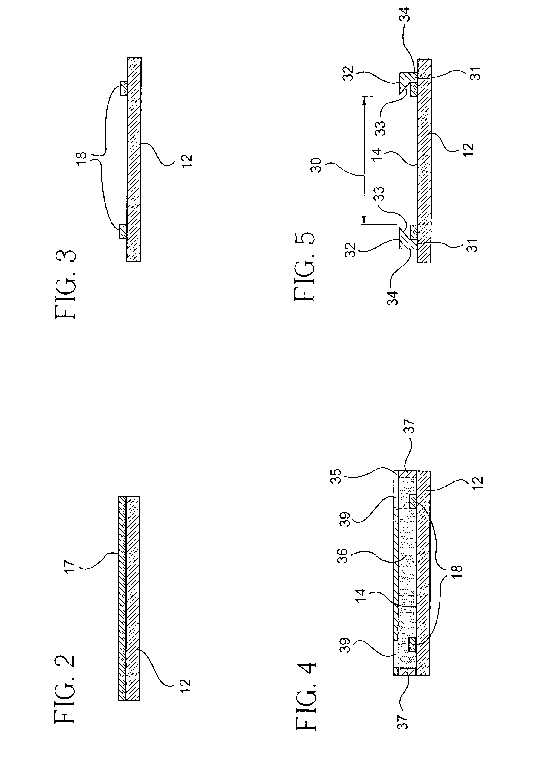
[0026] According to certain embodiments of the invention, fabrication of chambers is accomplished by utilizing conventional photolithographic techniques that are typically used in the manufacture of optical and electronic devices. For example, the spacer element 18 can be formed using
spin coating techniques to deposit a layer of
photoresist 17 on the substrate 12 as shown in FIG. 2. Spin-
coating is known in the art of
electronics manufacture. Photolithographic techniques can then be used to remove a portion of the
photoresist to provide spacing elements 18 and form a reaction chamber in the
photoresist layer 17. It will be understood that other photo patternable materials such as polysiloxane film can be used instead of photoresist. Formation of the spacer element 18 by
spin coating allows the spacer element 18 to be formed to very precise dimensional tolerances, and spacer elements 18 having a height as small as 1 micron can be formed using
spin coating techniques. The spacer elements could also be made using other processes such as photolithographic processes.
[0027] The method of forming a biological or chemical reaction chamber also includes forming a flexible gripping element 28 including at least a pair of flexible, substantially parallel, spaced apart walls 31 and snap fitting a generally planar cover substrate between the spaced apart walls. A flexible gripping element can be formed by first applying an adhesion
promoter such as
trichlorosilane to the inner surface 14 of the substrate 12. Then, a photo-definable
polymer or
monomer 36 can coated on top or inner surface of the substrate 12 and temporary spacers 37 can be placed between the substrate to define the height of the gripping elements. A photo
mask 35 and
ultraviolet light (not shown) can be used to selectively cure the
polymer or
monomer through apertures 39 defined in the photo
mask and form at least a pair of substantially parallel walls 31. The substantially parallel walls having inwardly sloping surfaces 33 provide a gripping element that allows a planar cover substrate to be easily snapped on or off the base substrate 12 and enclose the chamber. In preferred embodiments, the spaced apart walls 31 are formed by
photolithography, for example, by curing a
monomer or
polymer 33 through a
mask 35 having apertures 39. The temporary spacer 37 can be used to define the overall height of the walls 31 during formation of the gripping elements.
[0033] A photo mask or image mask bearing a pattern of opaque areas which allow UV light to pass through only in the areas which comprise the pattern of the flexible gripping element is positioned above monomer or polymer layer, and WV light (not shown) as for example from a mercury or
xenon lamp, is directed to fall on the surface of image mask or
photomask. UV light which passes through the clear areas of mask causes a photopolymerization reaction in the regions of monomer or polymer layer which are directly under those image areas. No photoreaction occurs in those areas of monomer or polymer layer which are shielded from the UV light by the opaque areas of image mask. After
irradiation by UV light, image mask is removed and the unreacted monomer or polymer can washed away with a suitable
solvent such as
acetone or
methanol, leaving a photopolymerized gripping on the base substrate. The gripping elements include a pair of spaced apart walls 31. According to certain embodiments, the walls 31 have a substantially trapezoidal cross section. The unique inverted trapezoidal geometry can be achieved by the choice of proper conditions of
irradiation. The optical absorption of the unreacted monomer layer at the wavelengths of the UV light must be high enough, such that a gradient of UV
light intensity is established through the film. That is, the amount of UV light available in the monomer layer to cause the
initiation of the photoreaction will decrease from the top, or the image mask side, towards the bottom, or the substrate side, due to the finite absorption of the monomer layer. This gradient of UV light causes a gradient in the amount of photopolymerization reaction that occurs from top to bottom, resulting in the unique geometry of the developed polymer structure.


