Method for starting a permanent magnet single-phase synchronous electric motor and electronic device for implementing said method

a synchronous electric motor and single-phase technology, applied in the direction of synchronous motor starters, multiple motor speed/torque control, electric pulse generators, etc., can solve the problems of high degree of complexity, substantial production and installation costs, and difficult starting of synchronous motors, so as to prevent the demagnetisation of the rotor, increase the intensity, and reduce the initiation angle

Active Publication Date: 2012-04-24
ASKOLL HLDG SRL
View PDF11 Cites 14 Cited by
  • Summary
  • Abstract
  • Description
  • Claims
  • Application Information

AI Technical Summary

Benefits of technology

[0018]The control logic described above, also able to be actuated in sensorless mode with low-cost components, allows simple and effective starting of a single-phase synchronous electric motor.
[0041]In particular, it has been seen how it is advantageous to decrease the initiation angle during the series of starting impulses, which thus have progressively increasing intensity.

Problems solved by technology

As known, synchronous motors, whilst benefiting from a high energy efficiency and excellent stability of the operating speed, have a substantial drawback linked to their difficulty in starting.
In practice, in order to allow said frequency coupling mechanical and / or electronic technical provisions are adopted, which of course involve a substantial production and installation cost.
On the other hand said circuits, whilst satisfactorily solving the problem of starting the motor, have a high degree of complexity and thus substantially affect the overall cost of the device.
Indeed, they have been developed and optimised for three-phase machines, and they are excessively onerous and unsuitable for controlling two-phase synchronous motors and above all low-power single-phase synchronous motors.
However, such a solution cannot be implemented on single-phase motors, given that the counter electromotive force on them cannot be obtained when the current in the phase winding is different from zero.
The mechanical provisions used for the purpose do however bring further problems of energy efficiency and noise.

Method used


Image

  • Method for starting a permanent magnet single-phase synchronous electric motor and electronic device for implementing said method
  • Method for starting a permanent magnet single-phase synchronous electric motor and electronic device for implementing said method
  • Method for starting a permanent magnet single-phase synchronous electric motor and electronic device for implementing said method

Examples


Embodiment Construction

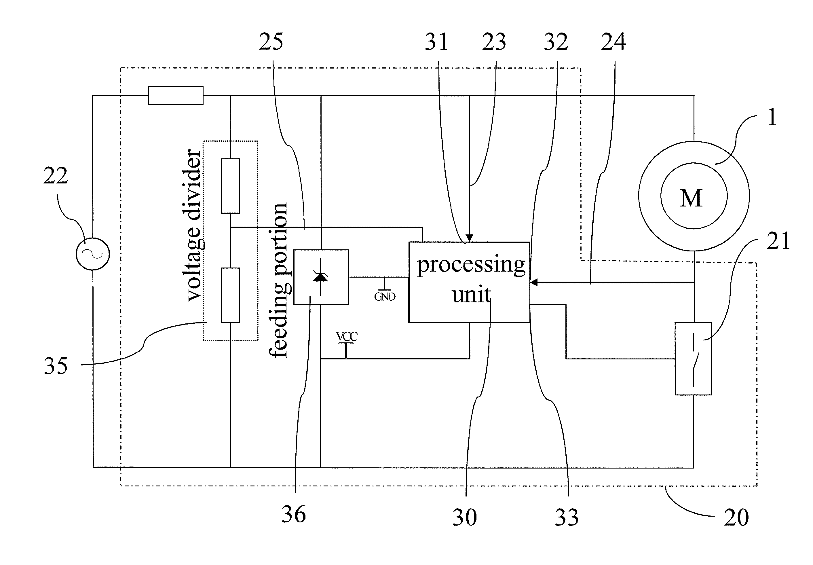
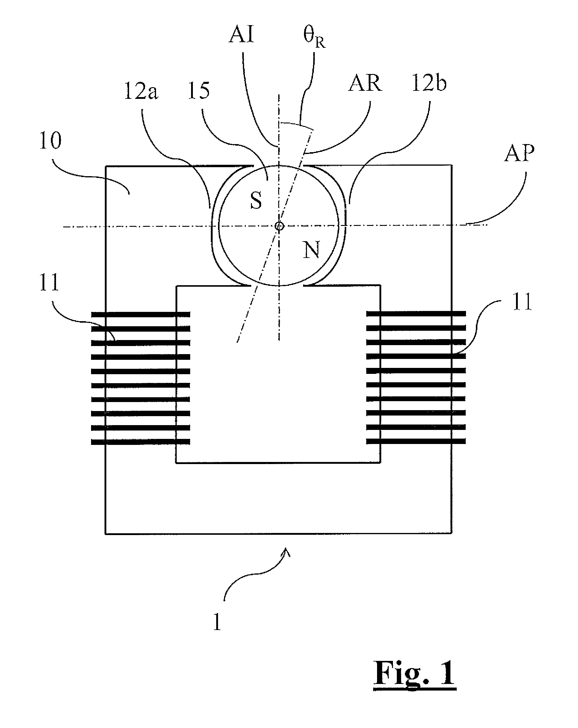
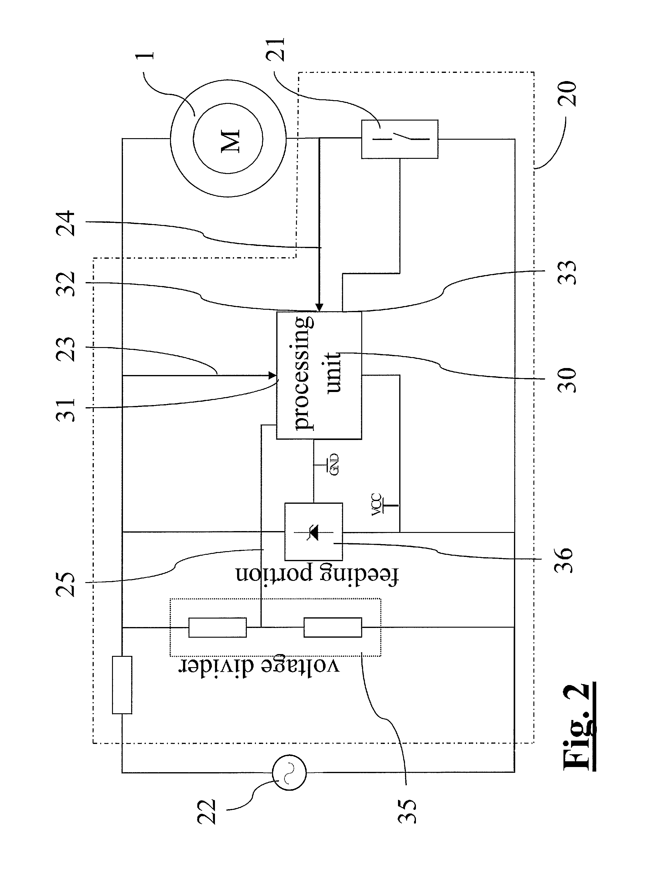
[0053]With reference to the attached FIG. 1, reference numeral 1 identifies a single-phase synchronous motor using permanent magnets, comprising a stator 10 and a cylindrical rotor15 able to rotate with respect to it.

[0054]The stator 10 defines a magnetic circuit that closes on the rotor 15, rotatably arranged between a first 12a and a second 12b polar expansion of the stator itself. The stator has two windings 11 fed by an electronic device 20.

[0055]The rotor 15 comprises a permanent magnet arranged so as to define two diametrically opposite magnetic poles on the outer periphery of the element. With the term rotor axis AR we shall define a diameter of the rotor lying on the ideal plane of separation between the poles thus defined.

[0056]The polar expansions 12a, 12b, arranged according to a polar axis AP of the stator 10, are distinguished by a morphological asymmetry, so that the rotor 15 at rest is arranged with rotor axis AR inclined by an angle of asymmetry θR with respect to an...


PUM


Abstract

Method for starting a single-phase synchronous electric motor using permanent magnets with simple and cost-effective implementation, said method comprising a step of application of a control logic of the switch that provides a first and a second condition for switching on:the first condition being verified when a detected counter electromotive force signal has the same sign as an electrical grid voltage signal;the second condition being verified when said counter electromotive force signal has the same sign as its first derivative value.

Description

CROSS-REFERENCE TO RELATED APPLICATIONS[0001]The present application claims priority to European Patent Application No. 10425250.7, filed Jul. 23, 2010, the entirety of which is incorporated herein by reference.FIELD OF APPLICATION[0002]The present invention refers, in its most general aspect, to a method for starting a single-phase permanent magnet synchronous electric motor, as well as to an electronic device able to be associated with an electric motor to implement said starting method.[0003]In particular, the method concerns the starting of single-phase synchronous electric motors used in applications characterised by a great need to reduce cost and bulk. For example, it concerns the starting of electric motors used in domestic appliances such as washing machines and dishwashers.PRIOR ART[0004]As known, synchronous motors, whilst benefiting from a high energy efficiency and excellent stability of the operating speed, have a substantial drawback linked to their difficulty in star...

Claims


Application Information

Patent Timeline
Patent Type & Authority Patents(United States)
IPC IPC(8): H02P6/18H02P6/22
CPCH02P1/465H02P6/008H02P6/182H02P27/024H02P6/26
Inventor MARIONI, ELIO
Owner ASKOLL HLDG SRL
Why Eureka
Try Eureka