
A rigid solid-state modulation switch module and its combined circuit

A modulation switch, solid state switch technology, applied in electronic switches, electrical components, pulse technology and other directions, to achieve the effect of convenient application

Active Publication Date: 2017-12-29
CHINA ELECTRONIC TECH GRP CORP NO 38 RES INST
View PDF5 Cites 0 Cited by
  • Summary
  • Abstract
  • Description
  • Claims
  • Application Information

AI Technical Summary

Problems solved by technology

[0004] In order to overcome the design and application difficulties faced by current solid-state switching devices in combined applications, shorten the development cycle, improve the reliability of solid-state switches, and flexibly adapt to the needs of various applications, the invention provides a rigid solid-state modulation switch module and its combination circuit, rigid solid-state modulation switch module has the characteristics of flexible adaptation to working voltage requirements, convenient use of modules in series, long life, and high reliability

Method used


Image

  • A rigid solid-state modulation switch module and its combined circuit
  • A rigid solid-state modulation switch module and its combined circuit
  • A rigid solid-state modulation switch module and its combined circuit

Examples


Embodiment Construction

[0024] The technical solutions in the embodiments of the present invention will be clearly and completely described below in conjunction with the accompanying drawings in the embodiments of the present invention. Obviously, the described embodiments are only a part of the embodiments of the present invention, rather than all the embodiments. Based on the embodiments of the present invention, all other embodiments obtained by those of ordinary skill in the art without creative work shall fall within the protection scope of the present invention.

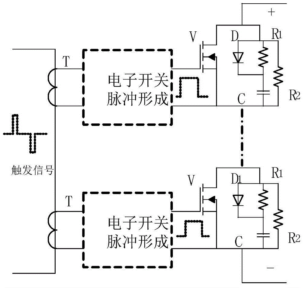
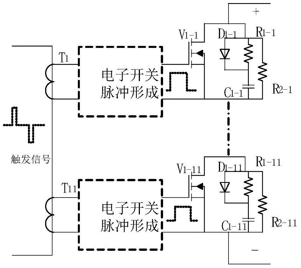
[0025] See figure 1 , The rigid solid-state modulation switch module of the present invention includes a trigger transformer T having at least two secondary windings, at least two switching device components corresponding to the at least two secondary windings, and a heat sink (not shown). Each switching device component includes an electronic switching circuit K, a solid-state switching device V, a static voltage equalization circuit, an...


PUM


Abstract

The invention discloses a rigid solid-state modulation switch module and a combined circuit thereof. The switch module includes a trigger transformer with at least two secondary windings, at least two switch device assemblies. Each switching device assembly includes an electronic switching circuit, a solid-state switching device, a static voltage equalizing circuit, and a dynamic voltage equalizing circuit. The two input ends of the electronic switch circuit are respectively connected to the two ends of the corresponding secondary winding, the high voltage end of the two output ends of the electronic switch circuit is connected to the grid of the solid state switching device, and the low voltage end is connected to the solid state switch Device source connection. Both the static voltage equalizing circuit and the dynamic voltage equalizing circuit are connected in parallel between the source and the drain of the solid-state switching device. The electronic switch circuit is used to form the trigger pulse of the solid-state switching device from the positive and negative pulse trigger signals flowing through the primary of the trigger transformer. The invention also discloses a combined circuit formed by connecting several modules in series, in parallel, or in both series and parallel.

Description

Technical field [0001] The invention relates to pulse modulation switches of pulse modulators in pulse radar transmitters, electronic accelerators and other devices, as well as high-voltage direct current switches, etc., in particular to a rigid solid-state modulation switch module and a combined circuit thereof. Background technique [0002] Before the emergence of metal oxide field effect transistors (MOSFET) and insulated gate bipolar transistors (IGTBT) and their application technology matured, hydrogen charging thyristors were almost used in pulse modulators in radar transmitters and electron accelerators. , Vacuum electronic triode or similar vacuum electronic switch tube as pulse modulation switch. Because these electronic tubes not only have life problems, they also need to provide filament power and relatively large-power trigger signals, so that these vacuum electronic switching tube pulse modulation switches and their pulse modulators have short life, low reliability a...

Claims


Application Information

Patent Timeline
Patent Type & Authority Patents(China)
IPC IPC(8): H03K17/687
Inventor 张建华王旭明邵世东陶小辉张丽君徐玉存
Owner CHINA ELECTRONIC TECH GRP CORP NO 38 RES INST
Learn More