Shadow casting technique based automatic shoot positioning correcting system and method

A technology of automatic calibration and projection technology, applied in the field of projection, can solve problems such as laser and live ammunition positioning errors, lack of familiarity with professional technology, long calibration working hours, etc., and achieve high practical efficiency

Active Publication Date: 2015-06-03
上海亿湾特训练设备科技有限公司 +2
View PDF4 Cites 10 Cited by
  • Summary
  • Abstract
  • Description
  • Claims
  • Application Information

AI Technical Summary

Problems solved by technology

But when there are several, a dozen or dozens of projectors, or when the screen is divided into upper and lower layers and the height reaches more than ten meters, there are hundreds to thousands of points that need to be marked on each screen. Well, since the installation positions of projectors, laser positioning cameras, thermal imagers, etc. will change the position of the projection screen due to factors such as seasonal temperature changes, ground subsidence, deformation of installation fixtures, and human touch, etc., this It will cause the deviation of the positioning of the original marking points, and the manual calibration of the full screen area again will cause the operator on the user side to be unable, unwilling or very difficult due to the influence of factors such as very long calibration hours, shortage of climbing equipment, and lack of familiarity with professional technology. Timely calibration of positioning is rarely performed, which will easily cause large positioning errors between laser and live ammunition during actual shooting training

Method used


Image

  • Shadow casting technique based automatic shoot positioning correcting system and method
  • Shadow casting technique based automatic shoot positioning correcting system and method
  • Shadow casting technique based automatic shoot positioning correcting system and method

Examples


Embodiment Construction

[0044]In order to more clearly illustrate the technical solutions in the embodiments of the present invention or the prior art, the following will briefly introduce the drawings that need to be used in the description of the embodiments or the prior art. Obviously, the accompanying drawings in the following description are only These are some embodiments of the present invention. Those skilled in the art can also obtain other drawings based on these drawings without creative work.

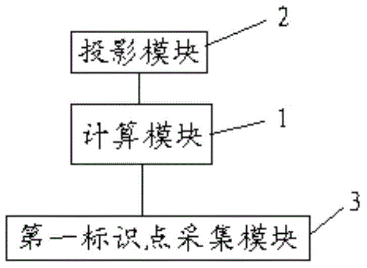
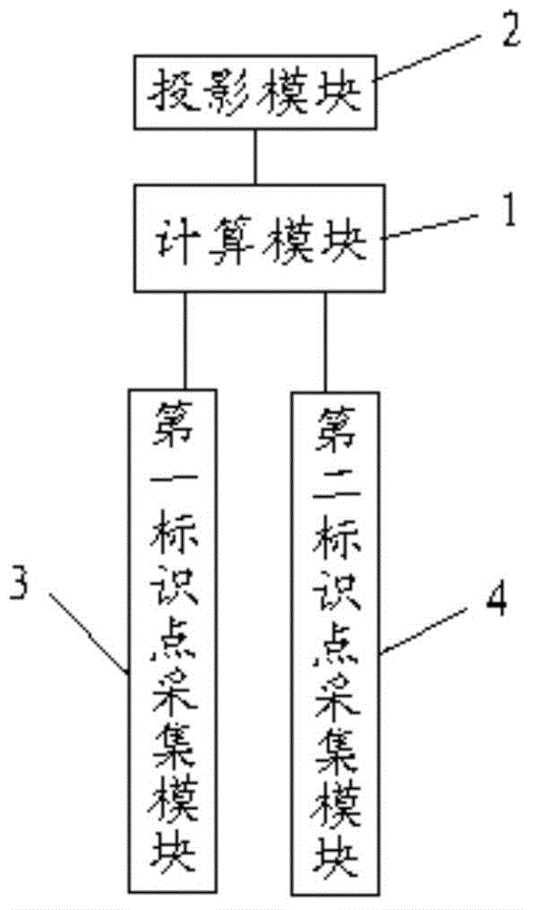
[0045] figure 1 It is a structural block diagram of the shooting positioning automatic correction system based on the projection technology of the present invention. As a specific embodiment of the present invention, such as figure 1 As shown, a shooting positioning automatic correction system based on projection technology includes a calculation module 1, a projection module 2, and a first marker point acquisition module 3;

[0046] The projection module 2 acquires the first coordinate data, and...


PUM


Abstract

The invention provides a shadow casting technique based automatic shoot positioning correcting system and method. The system comprises a calculating module, a shadow casting module and a first identification point acquiring module, wherein the shadow casting module acquires first coordinate data, and casts shadow of a positioning identification point according to the first coordinate data; the first identification point acquiring module acquires the positioning identification point, and obtains second coordinate data; the calculating module calculates the first coordinate data and the second coordinate data to obtain third coordinate data; the shadow casting module casts shadow of a first correcting identification point according to the third coordinate data, and enables the first correcting identification point to be coincided with the positioning identification point. The shadow casting technique based automatic shoot positioning correcting system and method are convenient to operate, and have relatively outstanding technical effects.

Description

technical field [0001] The invention relates to the field of projection technology, in particular to an automatic positioning correction technology of the projection technology. Background technique [0002] In the equipment field of projected image shooting training, the projected static target image or dynamic scene image is provided by a computer program to a projector and projected onto a training screen to generate. Among them, the laser emission point signal for simulating laser gun shooting training is obtained by monitoring the entire projected picture range by using a camera device that can detect this wavelength of laser light. The signal of the impact point of live ammunition gun shooting is obtained by collecting the heat signal generated by the friction between the bullet and the rubber screen through thermal imaging equipment. In the field of equipment calibration using computer projection images for shooting training, there is a problem of correcting the posi...

Claims


Application Information

Patent Timeline
Patent Type & Authority Applications(China)
IPC IPC(8): H04N5/74H04N9/31G06T7/00
Inventor 王敬雷王曳晨
Owner 上海亿湾特训练设备科技有限公司
Why Eureka
Try Eureka