Vertical solid and liquid separation device
A solid-liquid separation, vertical technology, applied in the direction of presses, manufacturing tools, etc., can solve the problems of high cost, poor slag discharge, difficult to clean the feeding port, etc., to reduce the use of parts, simple structure, disassembly and assembly handy effect
- Summary
- Abstract
- Description
- Claims
- Application Information
AI Technical Summary
Problems solved by technology
Method used
Image

Examples
Embodiment 1
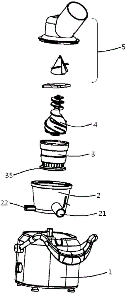
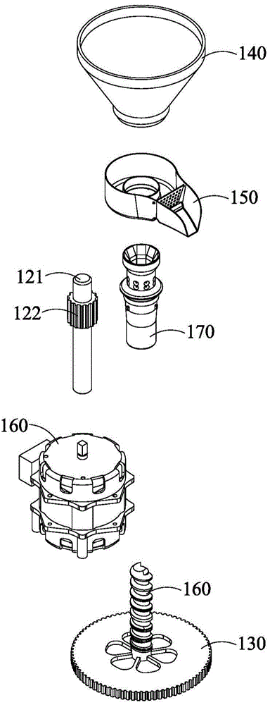
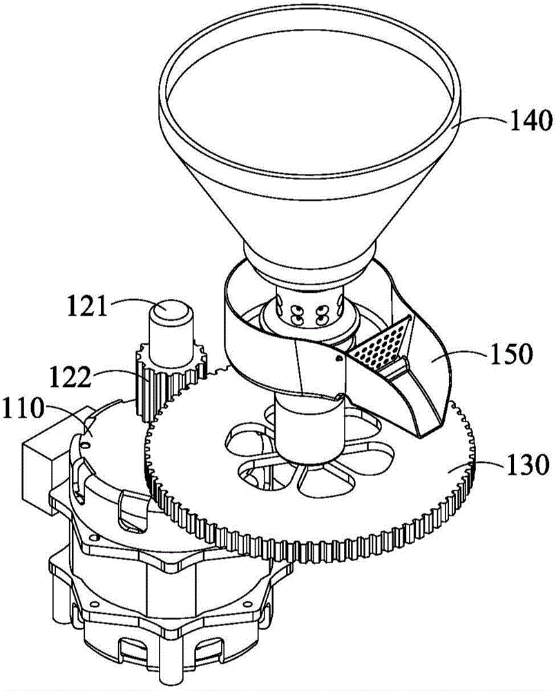
[0051] The oil press of this embodiment is an oil press that drives the pressing rod at the slag discharge end to extract oil. like Figure 2A , 2B As shown in and 2C, the body of the oil press includes a drive mechanism, a squeeze rod 160, a squeeze sleeve 170, a feed hopper 140, a gear plate 130 and an oil pan 150. The squeeze rod 160 is rotatably assembled in the squeeze sleeve 170, and the closed cavity between the squeeze sleeve 170 and the squeeze rod 160 forms a squeeze chamber. The driving mechanism includes a motor 110 , a gear transmission shaft 121 and a transmission gear 122 . One end of the gear drive shaft 121 is mounted on the motor 110 , and the other end is equipped with a transmission gear 122 , and the transmission gear 122 meshes with the gear plate 130 . The gear plate 130 is a toothed disc with holes, and the center of the gear plate 130 is connected with the bottom end of the squeezing rod 160 .
[0052] When the oil press is working, the oil in the ...
Embodiment 2
[0057] The oil press of this embodiment is an oil press that drives the pressing rod at the feed end to extract oil. like Figure 5A and 5B As shown, the body of the oil press includes a driving mechanism, a squeeze rod 460 , a squeeze sleeve 470 , a gear plate 430 and a feed hopper 440 . The squeeze rod 460 is rotatably assembled in the squeeze sleeve 470 , and the closed cavity formed by the squeeze sleeve 470 and the squeeze rod 460 forms a squeeze chamber. The driving mechanism includes a motor 410 , a gear transmission shaft 421 and a transmission gear 422 . One end of the gear transmission shaft 421 is installed on the motor 410 , and the other end is equipped with a transmission gear 422 , and the transmission gear 422 meshes with the gear plate 430 . The top of the squeezing rod 460 protrudes from the feed hopper 440, the gear plate 430 is a disc, and the center of the gear plate 430 is connected with the top of the squeezing rod 460.
[0058] When the oil press is...
Embodiment 3
[0066] The oil press of this embodiment is an oil press that drives the press cover to rotate oil, such as Figure 9A and 9B As shown, the oil press includes a drive mechanism, a feed hopper 740, a squeeze rod 760 and a screw squeeze sleeve 770 and a worm wheel 730 matched therewith. The open space where the pressing sleeve 770, the pressing rod 760 and the feed hopper 740 cooperate forms the feeding section, and the closed inner cavity where the pressing sleeve 770 cooperates with the pressing rod 760 forms a pressing chamber, including the conveying section in the upper part and the pressing section in the middle part and The lower part of the cake section. The conveying section accepts the oil at the inlet, conveys and pre-presses the oil, and the oil in this section does not produce oil during pressing; the pressing section from the beginning of oil production to the end of oil production is used to press oil to produce oil From no oil to the slag outlet end is the cake ...
PUM
 Abstract
Description
Claims
Application Information
 - Generate Ideas
- Intellectual Property
- Life Sciences
- Materials
- Tech Scout
- Unparalleled Data Quality
- Higher Quality Content
- 60% Fewer Hallucinations
Browse by: Latest US Patents, China's latest patents, Technical Efficacy Thesaurus, Application Domain, Technology Topic, Popular Technical Reports.
© 2025 PatSnap. All rights reserved.Legal|Privacy policy|Modern Slavery Act Transparency Statement|Sitemap|About US| Contact US: help@patsnap.com