Automatic lifting device of ball-cage type constant velocity universal joint holders

A constant velocity universal joint and automatic lifting technology, which is applied in the direction of lifting devices, lifting frames, transportation and packaging, etc., can solve the problems of low efficiency and unsatisfactory automatic lifting, and achieve a high degree of automation and real-time controllable feeding and discharging speeds , the effect of reducing loss

Active Publication Date: 2015-06-10
HANGZHOU YUCE TECH
View PDF5 Cites 6 Cited by
  • Summary
  • Abstract
  • Description
  • Claims
  • Application Information

AI Technical Summary

Problems solved by technology

In the prior art, the lifting method of the ball cage type constant velocity universal joint cage is often carried out manually, which cannot meet the needs of au

Method used


Image

  • Automatic lifting device of ball-cage type constant velocity universal joint holders
  • Automatic lifting device of ball-cage type constant velocity universal joint holders
  • Automatic lifting device of ball-cage type constant velocity universal joint holders

Examples


Embodiment Construction

[0030] The present invention will be further described below in conjunction with accompanying drawing:

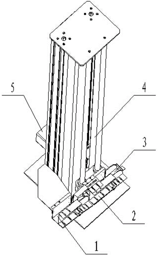
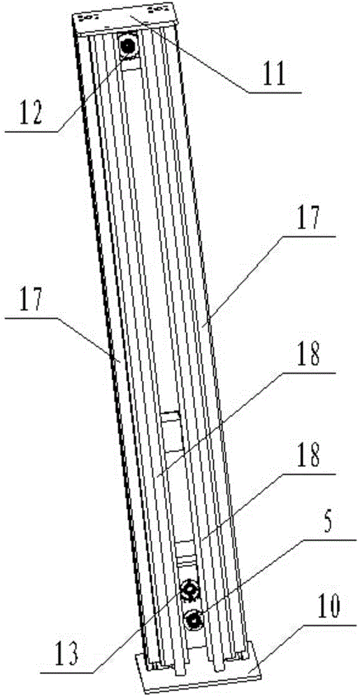
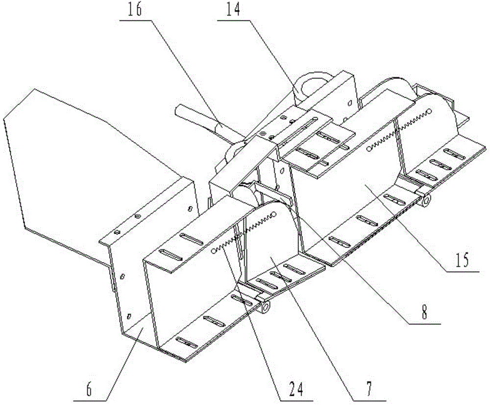
[0031] figure 1 It is a schematic diagram of the overall structure of a cage type constant velocity universal joint cage automatic lifting device of the present invention; figure 2 It is a structural schematic diagram of the lifting mechanism and the drive motor of the present invention; image 3 It is an oblique top view of the three-dimensional structure of the feeding device, lifting platform and unloading device of the present invention; Figure 4 It is an oblique bottom view of the three-dimensional structure of the feeding device, lifting platform and unloading device of the present invention; it can be seen that:

[0032] A ball cage type constant velocity universal joint cage automatic lifting device, including a feeding device 1, a lifting platform 2, an unloading device 3, a lifting track 4 and a driving motor 5;

[0033] The feeding device 1 includes a fixed ...


PUM


Abstract

The invention discloses an automatic lifting mechanism of holders, so as to lift the holders one by one automatically. The automatic lifting mechanism comprises a feeding device, a lifting platform, a discharging device, a lifting rail and a driving motor. The automatic lifting mechanism is simple and compact in structure, can achieve the one-by-one feeding and the short-distance lifting of ball-cage type constant velocity universal joint holders through a simple mechanical structure, has high automation degree, and reduces the labor consumption.

Description

technical field [0001] The invention relates to a lifting device, more specifically, it designs an automatic lifting device for a ball cage type constant velocity universal joint cage. Background technique [0002] The cage is a bearing part that partially wraps all or part of the rolling elements and moves with them; it is used to isolate the rolling elements and guide the rolling elements to keep them in the bearing. Ball cage constant velocity universal joints are widely used because of their strong bearing capacity, compact structure, and easy disassembly and assembly. , known for its high dimensional accuracy requirements. The ball cage type constant velocity universal joint cage referred to in the present invention is a metal structural part whose internal and external performances are spherical and both ends are plane after turning and punching. When detecting pocket holes, it is often necessary to The cage is raised while rolling. In the prior art, the lifting met...

Claims


Application Information

Patent Timeline
IPC IPC(8): B65G29/02
CPCB65G47/74B66F3/02B66F3/44B66F7/12B66F7/28
Inventor 周海清单晓杭孙建辉励红峰
Owner HANGZHOU YUCE TECH
Why Eureka
Try Eureka