Eureka AIR delivers breakthrough ideas for toughest innovation challenges, trusted by R&D personnel around the world.

Flocculating basin with arc blade vortex generators and flocculating method thereof

A technology of arc-shaped blades and generators, which is applied in the field of water treatment, can solve the problems that the flocculation equipment cannot be adjusted flexibly, the spiral flocculator cannot be adjusted, and the flocculation equipment cannot be adjusted, etc. It achieves flexible and convenient adjustment, simple structure, and convenient maintenance and cleaning Effect

Active Publication Date: 2015-06-10
HANGZHOU DIANZI UNIV
View PDF9 Cites 14 Cited by
  • Summary
  • Abstract
  • Description
  • Claims
  • Application Information

AI Technical Summary

Problems solved by technology

However, the spiral flocculator cannot be flexibly adjusted according to the flow and velocity of the water flow, and the flocculation effect is not ideal
[0007] It can be seen that the flocculation equipment on the existing market is relatively old, and many parameters are designed according to the previous water quality conditions, and the flocculation equipment cannot be flexibly adjusted according to the flow and velocity of water; a large shear force is easily formed near the equipment, making Larger flocs that have been formed are easily chopped
Now there is an urgent need for a set of design solutions that can solve the problem that the flocculation equipment cannot be adjusted flexibly and the flocs are easily chopped during the flocculation process.

Method used


Image

  • Flocculating basin with arc blade vortex generators and flocculating method thereof
  • Flocculating basin with arc blade vortex generators and flocculating method thereof
  • Flocculating basin with arc blade vortex generators and flocculating method thereof

Examples


Embodiment Construction

[0032] The present invention will be further described below in conjunction with the accompanying drawings and embodiments.

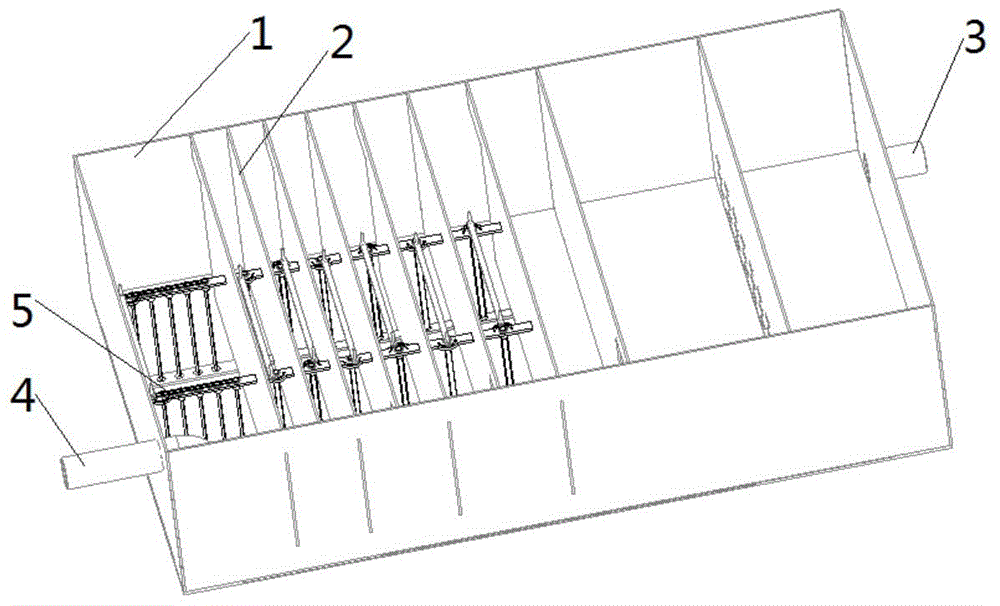
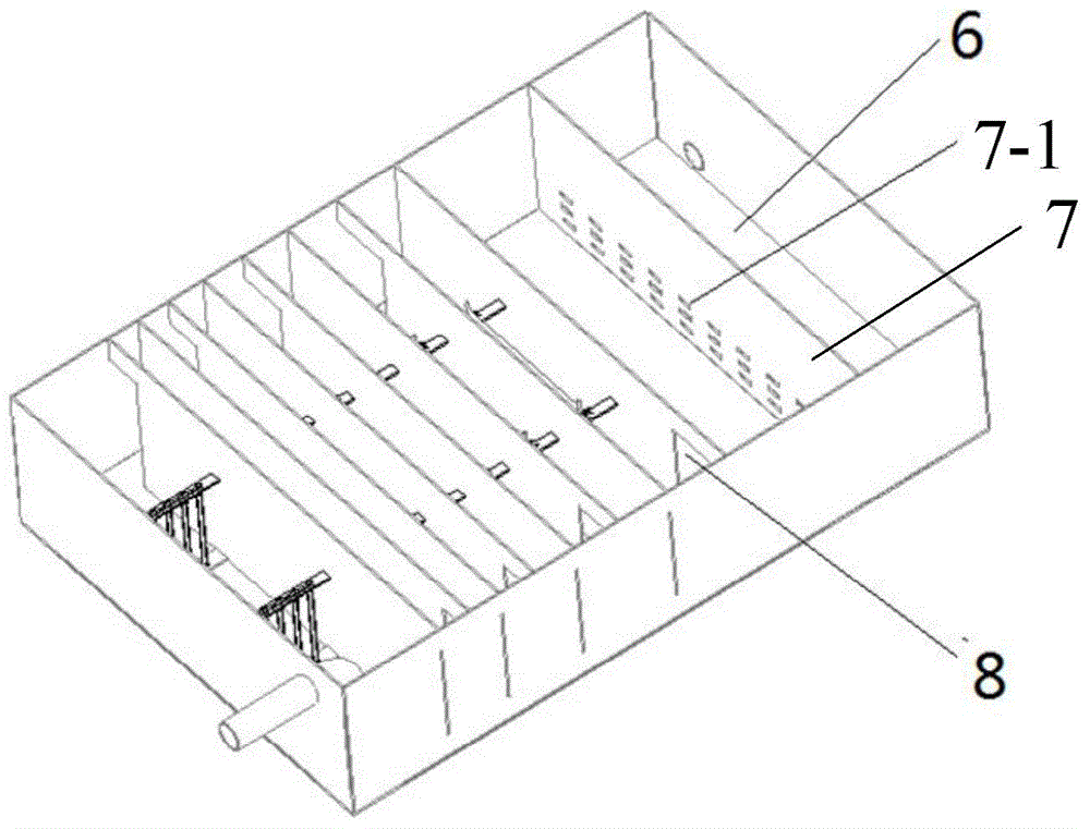
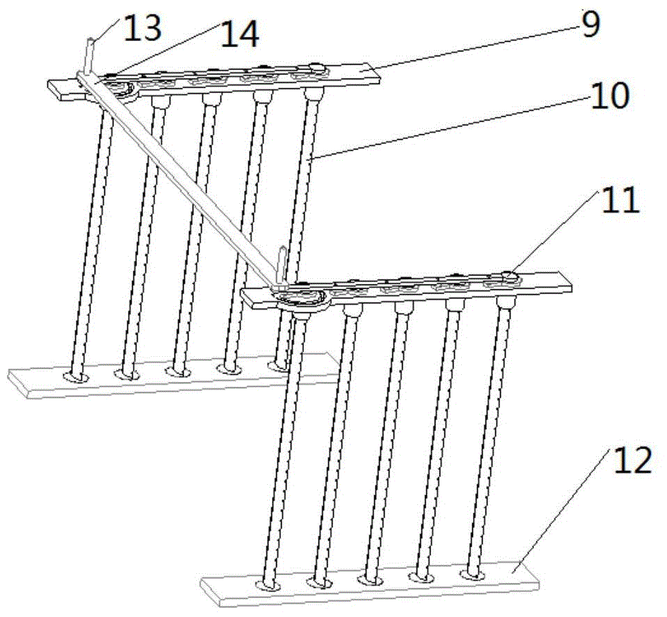
[0033] Such as figure 1 and 2 As shown, the flocculation tank with arc-shaped blade vortex generators includes a flocculation tank body 1 and a blade vortex generator 5; the flocculation tank body 1 is provided with an inlet 4 and an outlet 3; the flocculation tank body is surrounded by sedimentation partitions 7 and n A corridor partition 2 is divided into n+1 corridors and a sedimentation tank 6, wherein n=9; the sedimentation tank is directly connected to the outlet 3; the sedimentation partition 7 is provided with diversion hole groups 7 arranged in a matrix -1, two adjacent corridor partitions 2 have channel openings 8 on different sides; except for the corridor adjacent to the sedimentation partition, each corridor is provided with a plurality of vane vortex generators at intervals along the length of the corridor Device 5; along the direction f...


PUM


Abstract

The invention discloses a flocculating basin with arc blade vortex generators and a flocculating method thereof. A design scheme for solving the problems that a flocculating device cannot be flexibly adjusted, and a flocculating constituent in the flocculating process is prone to being shredded is in urgent need at present. A flocculating basin body is divided into n+1 galleries and one settling pond, and the multiple arc blade vortex generators are arranged in all the galleries except for the gallery close to a settling partition plate. The flocculating method comprises the steps that raw water and a chemical flow into the flocculating basin body after being mixed in a coagulation pipe and passes through the galleries in a turbulence and vortex mode to enter the settling pond through guiding hole sets of the settling partition plate, and the flocculation is constantly accumulated and finally deposited at the bottom of the settling pond; blade angle adjusting devices are constantly adjusted, treated water samples are collected at an outlet to carry out water turbidity measurement, and blade deviation angles matched with the turbulence flow and the flow speed are acquired. The rotating angles of arc blades around a center shaft can be adjusted according to the water flow and the flow speed, and therefore the water flow vortex degree and intensity can be adjusted, and the flocculating process is promoted.

Description

technical field [0001] The invention belongs to the technical field of water treatment, and in particular relates to a flocculation tank with a vortex generator with arc-shaped blades and a flocculation method thereof. Background technique [0002] Humans have been treating water for quite a long time. The agglomeration of suspended particles in water or liquid, or the formation of flocs, accelerates the coagulation of particles and achieves the purpose of solid-liquid separation. This phenomenon or operation is called flocculation. Usually, flocculation is implemented by adding an appropriate flocculant, whose function is to adsorb particles and "bridge" between particles, thereby promoting agglomeration. [0003] The particle size of suspended matter and limb matter in natural water is very small. In order to remove these substances, coagulation is usually used, that is to say, an appropriate coagulant is added to the raw water, and after thorough mixing, the stability o...

Claims


Application Information

Patent Timeline
IPC IPC(8): C02F1/52
Inventor 聂欣俞衡谷王徐江荣吕明路一丁李萌蔚
Owner HANGZHOU DIANZI UNIV
Why Eureka
Eureka Blog
Learn More