
Slider-crank material penetrating mechanism installed in same plane

A crank slider and plane technology, which is applied to sewing machine components, sewing machine needle seats, textiles and papermaking, etc., can solve problems such as noise pollution, vibration shock, and difficulty in ensuring the parallelism between the chute and the needle bar groove, etc. Small vibration and noise, reduce the effect of severe vibration

Inactive Publication Date: 2015-06-10
JIANGSU WANGONG TECH GRP CO LTD
View PDF7 Cites 0 Cited by
  • Summary
  • Abstract
  • Description
  • Claims
  • Application Information

AI Technical Summary

Problems solved by technology

For example, the motion inertia of the slider is much smaller than that of the needle bar, such as Figure 8 As shown, the positioning of the chute only depends on two screws, it is difficult to ensure the parallelism between the chute and the needle bar groove, and the movement results in periodic external force, which becomes the excitation source of vibration
Copying the mechanism of the low-speed machine, the mechanism itself has become a design defect. In principle, the low-speed mechanism cannot be used on the high-speed machine. The design defect produces vibration shock and noise pollution, which is also the main reason for the backwardness of domestic sewing machines.

Method used


Image

  • Slider-crank material penetrating mechanism installed in same plane
  • Slider-crank material penetrating mechanism installed in same plane
  • Slider-crank material penetrating mechanism installed in same plane

Examples


Embodiment Construction

[0032] The present invention will be described in detail below with reference to the accompanying drawings and in combination with embodiments.

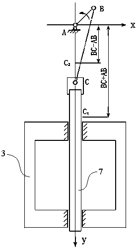
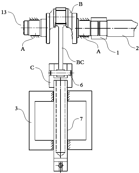
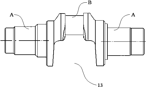
[0033] see figure 1 , figure 2 As shown, a crank slider threading mechanism installed on the same plane is composed of a crankshaft 13, a connecting rod BC and a needle bar slider C. The crankshaft 13 includes a minor axis A and a The bell crank B is rotated by 360° on the center line, the short shaft A is connected with the upper shaft 2 of the template sewing machine through the coupling 1, and the upper shaft 2 is supported on the top of the head box 3; the center line of the bell crank B is The distance from the center line of the minor axis A constitutes the crank AB, the crank throw B connects the big end 4 of the connecting rod BC, and the small end 5 of the connecting rod BC connects with the needle bar through the needle bar pin 6 The upper end of the slider C is connected, and the lower end of the needle bar slider C is...


PUM


Abstract

The invention discloses a slider-crank material penetrating mechanism installed in the same plane. The slider-crank material penetrating mechanism is composed of a crankshaft, a connection rod and a needle rod slide block. The crankshaft comprises a short shaft and a crank throw capable of rotating around the central line of the short shaft by 360 degrees. The short shaft is connected with an upper shaft of a template sewing machine. The upper shaft is supported by the top of a geared head. A crank is formed between the central line of the crank throw and the central line of the short shaft. The crank throw is connected with the large end of the connection rod. The small end of the connection rod is connected with the upper end of the needle rod slide block through a needle rod pin. The lower end of the needle rod slide block is connected with a needle rod which is supported by the middle and the bottom of the geared head. The technical requirements of all parts for the face-face parallelism and perpendicularity, the line-face parallelism and perpendicularity and the line-line parallelism and perpendicularity are more strict compared with the prior art, the violet vibration of the needle rod is reduced in the running process, vibration and noise of the sewing machine are greatly reduced, and the slider-crank material penetrating mechanism can meet the design requirements of the high-speed sewing machine, and is suitable for transformation of an existing material penetrating mechanism technology.

Description

technical field [0001] The invention relates to a material threading mechanism applied to a template sewing machine, in particular to a crank slider material threading mechanism installed on the same plane. Background technique [0002] The threading mechanism is the main source of vibration and noise of the template sewing machine. Like other machines, the trend of high-speed development of modern industrial sewing machines is clear, and the increasing high-speed increases the wear and tear of the moving rods of the various mechanisms that make up the sewing machine, which leads to more failures of the sewing machine. Therefore, the mechanism of the high-speed sewing machine must be newly designed. The feeding mechanism of the high-speed template sewing machine has changed the old form of the mechanical mechanism, and the drive mode of the servo motor or stepping motor is adopted. Other mechanical mechanisms of the template sewing machine must also have corresponding new d...

Claims


Application Information

Patent Timeline
Patent Type & Authority Applications(China)
IPC IPC(8): D05B55/14
Inventor 周平祝章琛
Owner JIANGSU WANGONG TECH GRP CO LTD
Learn More