T-shaped structure of wind power plant booster station in mountain area and arrangement method

A font-shaped structure and booster station technology, applied in substation rooms, industrial buildings, etc., can solve the problems of increasing initial investment in wind farms, large booster station footprint, and increased civil engineering volume. Small size, reduced initial investment, and the effect of saving civil construction costs

Inactive Publication Date: 2015-06-10
CEEC HUNAN ELECTRIC POWER DESIGN INST
View PDF6 Cites 0 Cited by
  • Summary
  • Abstract
  • Description
  • Claims
  • Application Information

AI Technical Summary

Problems solved by technology

[0005] At present, the layout of wind power booster stations in mountainous areas mostly adopts three-column or four-column layout structures. These two layout structures have the following disadvantages: (1) The living building and production building of the booster station are arranged separately, resulting in a large area occupied by the booster station. (2) The living building and the production building of the step-up station are arranged separately, which will inevitably increase the amount of civil works and increase the construction period; (3) The location of the power distribution device room of the station is far away from the production building, which will cause a decrease in the amount of cables increase, increase initial investment in wind farms

Method used


Image

  • T-shaped structure of wind power plant booster station in mountain area and arrangement method
  • T-shaped structure of wind power plant booster station in mountain area and arrangement method
  • T-shaped structure of wind power plant booster station in mountain area and arrangement method

Examples


Embodiment Construction

[0024] The present invention will be further described below in conjunction with drawings and embodiments.

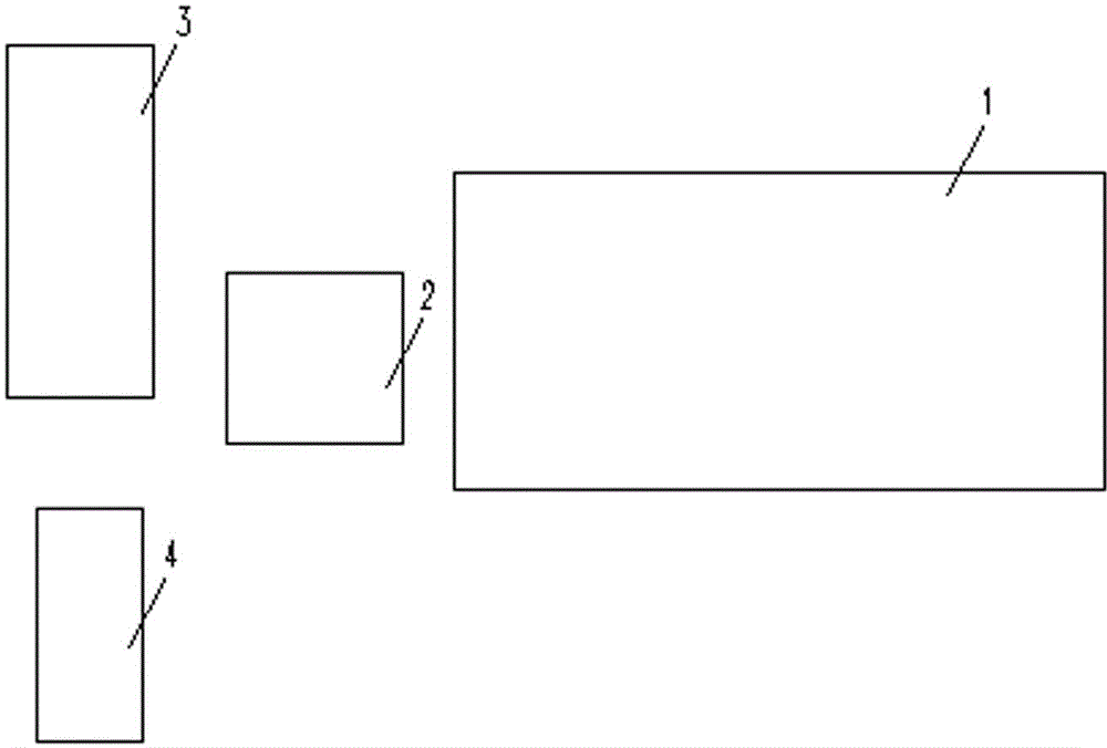
[0025] A "T"-shaped structure of a mountainous wind farm booster station (see figure 1 ), including complex building 1, main transformer 2, reactive power compensation device 3, domestic water treatment device 4, said complex building 1 and main transformer 2 are arranged on the same horizontal axis, reactive power compensation device 3, domestic water treatment device 4 Arranged on the same vertical axis, the horizontal axis is perpendicular to the vertical axis, and the vertical axis is located at the end of the horizontal axis, forming a "T" shape.

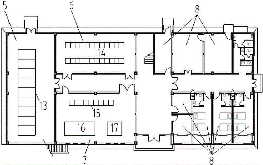
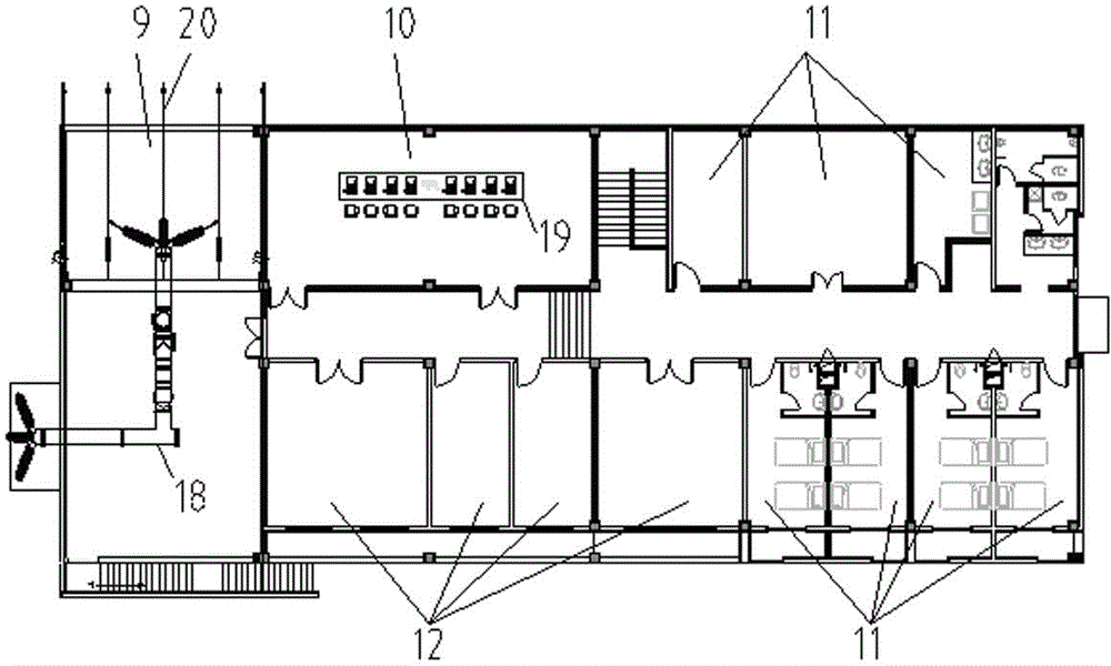
[0026] A method for arranging the "T"-shaped structure of the booster station of a wind farm in a mountainous area as described above (see figure 1 , figure 2 , image 3 ), including the following steps:

[0027] (1) Arrange the complex building 1 and the main transformer 2 in the step-up station in parallel, on the...


PUM


Abstract

The invention discloses a T-shaped structure of a wind power plant booster station in a mountain area and an arrangement method. The T-shaped structure comprises a complex building, a reactive compensation device, a main transformer and a living water treatment device. The T-shaped structure is characterized in that the complex building and the main transformer are arranged on the same transverse axis, the reactive compensation device and the living water treatment device are arranged on the same vertical axis, the transverse axis is perpendicular to the vertical axis, and the vertical axis is located at the end of the transverse axis, so that the T shape is formed. The invention further discloses the arrangement method of the T-shaped structure of the wind power plant booster station in the mountain area. When the T-shaped structure and the arrangement method are used, the main transformer is adjacent to a 35kV power distribution device and a GIS power distribution device, the length of cables and steel-cored aluminum strands needed by connection between the devices is reduced, and the initial investment is reduced. The booster station is compact in arrangement structure and small in occupied area, and saves expropriated land. In addition, all indoor electrical devices and houses for living are arranged in the complex building, the vertical space is utilized, the occupied area is effectively reduced, the civil engineering cost is saved, and the construction cycle is shortened.

Description

technical field [0001] The invention relates to an arrangement structure of a booster station of a wind farm in a mountainous area, which belongs to the design field of a booster station of a wind farm, and in particular relates to a "T"-shaped structure and an arrangement method of a booster station of a wind farm in a mountainous area. Background technique [0002] In recent years, the installed capacity of wind power has doubled every year, and the development momentum is strong. As far as our country is concerned, there are abundant wind resources in the north and northwest of our country. The natural conditions for building wind farms are good, and most of them are plain wind power. There are many differences between wind power in mountainous areas and wind power in plains. The site selection of the latter is simple, and the input cost of the latter is relatively low. Due to the complex climate and geographical environment of wind power in mountainous areas, more factor...

Claims


Application Information

Patent Timeline
Patent Type & Authority Applications(China)
IPC IPC(8): E04H5/04
CPCE04H5/04E04H5/02
Inventor 刘思佳杨红宁秀元胡军刘晓莲戴秋华
Owner CEEC HUNAN ELECTRIC POWER DESIGN INST
Why Eureka
Try Eureka