Special control system for producing oil-gas well plunger gas lift

A technology for control systems and oil and gas wells, applied in the direction of wellbore/well valve devices, wellbore/well components, production fluids, etc., which can solve the problem of single function of the controller

Inactive Publication Date: 2015-06-10
PETROCHINA CO LTD
View PDF4 Cites 10 Cited by
  • Summary
  • Abstract
  • Description
  • Claims
  • Application Information

AI Technical Summary

Problems solved by technology

[0004] These two controllers have single functions and cannot comprehensively use signals such as time, pressure, pre

Method used


Image

  • Special control system for producing oil-gas well plunger gas lift

Examples


Embodiment 1

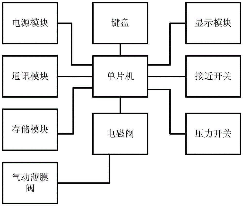
[0026] Embodiment 1: as figure 1 As shown, a special control system for plunger gas lift production in oil and gas wells, the power supply module, communication module, and storage module are connected to the single-chip microcomputer, the single-chip computer is connected to the keyboard, solenoid valve, display module, proximity switch and pressure switch, and the solenoid valve is connected to the pneumatic Membrane valve.

Embodiment 2

[0027] Embodiment 2: as figure 1 As shown, a special control system for plunger gas lift production of oil and gas wells, the plunger arrival signal output end of the proximity switch is connected with the plunger arrival signal input end of the single-chip microcomputer.

[0028] The pressure signal output end of the pressure switch is connected with the pressure signal input end of the single chip microcomputer.

[0029] The solenoid valve drive signal output end of the single chip microcomputer is connected with the solenoid valve drive signal input end.

[0030] The driving input port of the pneumatic membrane valve is connected with the driving output port of the pneumatic membrane valve of the electromagnetic valve.

[0031] The power supply module, the communication module, the memory module, the keyboard and the display module are respectively connected with the corresponding ports of the single chip microcomputer.

[0032] The well shut-in time and well open time ar...

Embodiment 3

[0036] Embodiment 3: as figure 1 As shown, a special control system for plunger gas lift production in oil and gas wells is mainly composed of power supply module, communication module, storage module, keyboard, display module, single chip microcomputer, proximity switch, pressure switch, solenoid valve, pneumatic membrane valve . The power supply module provides energy for the device; the communication module is used for indoor monitoring and communication with the upper computer; the storage module is used for storing setting parameters and field data; the keyboard is used for inputting instructions to the device; the display module is used for displaying information; It is used to receive the signal from the plunger to the wellhead; the pressure switch is used to receive the casing pressure and oil pressure signals of the wellhead; the single-chip microcomputer is used to communicate and control with each module; the solenoid valve receives the control signal of the single-...


PUM


Abstract

The invention discloses a special control system for producing an oil-gas well plunger gas lift, and belongs to the technical field of oil-gas extraction in oil-gas fields. A power supply module provides energy to a device; a communication module is communicated with an indoor monitor and an upper computer; a storage module is used for storing set parameters and site data; a keyboard is used for inputting instructions to the device; a display module is used for displaying information; a proximity switch is used for receiving signals of a plunger upwards moving to a well mouth; a pressure switch is used for receiving sleeve pressure and oil pressure signals of the well mouth; a single-chip is used for communicating and controlling all modules; an electromagnetic valve receives control signals of the single-chip to open/close a pneumatic film valve; and the pneumatic film valve controls the opening/closing of an oil-gas well. In order to enable the device power consumption to be the lowest, the electromagnetic valve adopts a two-position five-way double-electric-control electromagnetic valve. The control device for the plunger gas lift has the advantages of simple structure, convenience for parameter setting, safety, reliability and effective improvement of the output of the oil-gas well.

Description

technical field [0001] The invention relates to a special control system for plunger gas lift production of oil and gas wells, and belongs to the technical field of oil and gas recovery in oil and gas fields. Background technique [0002] Plunger gas lift is an artificial lift method that lifts formation fluid out of the ground through a plunger that circulates up and down in the tubing string. It forms a solid sealing interface between the lifted gas and the lifted liquid, making the lift The gas slippage and liquid drop during the lifting process are greatly reduced, thereby improving the instability of conventional gas lift and effectively improving the gas lifting efficiency. The key to this technology is the control of the plunger movement, that is, during the plunger gas lift production of the oil and gas well, the working system of the oil and gas well needs to be set according to the production status of the oil and gas well, that is, the opening and production time ...

Claims


Application Information

Patent Timeline
IPC IPC(8): E21B43/00
CPCE21B43/122E21B34/066E21B34/16
Inventor 孙冰恒王振松冯仁东刘友唐安达王志超
Owner PETROCHINA CO LTD
Why Eureka
Try Eureka