Engine valve driving mechanism and engine valve driving device

A technology of engine valves and driving mechanisms, which is applied in the direction of valve driving devices, engine components, machines/engines, etc., can solve the problems of inability to achieve optimal engine performance, large carbon dioxide emissions, and reduced service life. Effects on fuel consumption and service life extension

Active Publication Date: 2015-06-10
SAIC MOTOR
View PDF5 Cites 0 Cited by
  • Summary
  • Abstract
  • Description
  • Claims
  • Application Information

AI Technical Summary

Problems solved by technology

[0003] The valve driving mechanism and valve driving device in the prior art, because its valve lift is fixed or only has a few variable valve lifts, the engine performance can only be optimized under specific working conditions, which cannot make Engine performance is optimized over a wider range of operating conditions
As a result, the carbon dioxide emission of the valve assembly is large, the fuel consumption is high and the service life is reduced

Method used


Image

  • Engine valve driving mechanism and engine valve driving device
  • Engine valve driving mechanism and engine valve driving device
  • Engine valve driving mechanism and engine valve driving device

Examples


Embodiment Construction

[0038] The specific implementation manner of the present invention will be further described below in conjunction with the accompanying drawings.

[0039] The engine valve drive mechanism and valve drive device provided by the invention have continuously variable lift.

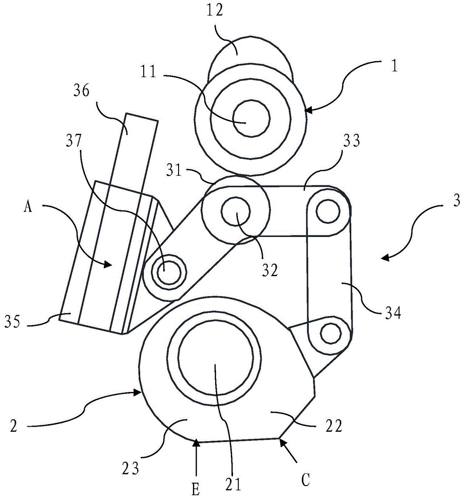
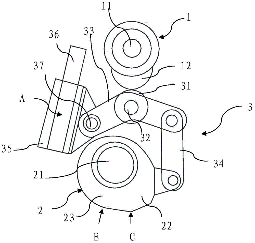
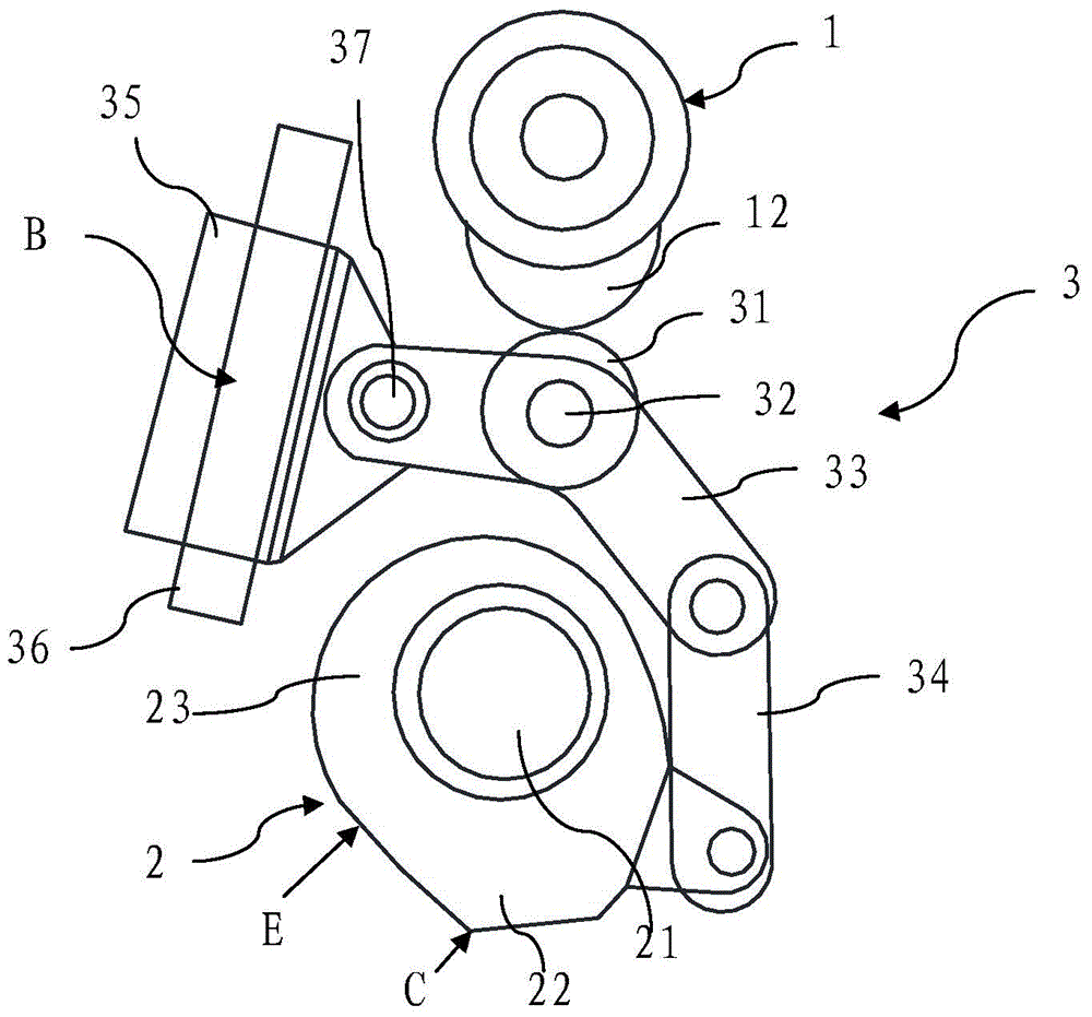
[0040] Such as Figure 1-3 As shown, the engine valve drive mechanism provided by the present invention includes a main camshaft 11, a main cam 1 mounted on the main camshaft 11, a control shaft 21 arranged in parallel with the main camshaft 11, and a control shaft 21 rotatably installed on the control shaft. On 21, it is used to drive the auxiliary cam 2 of engine valve opening and closing.

[0041] A connecting driving member 3 for driving the auxiliary cam 2 to rotate is connected between the main cam 1 and the auxiliary cam 2 .

[0042] The connecting drive member 3 includes a curved arm 33 , a connecting rod 34 , a trunnion 35 , a guide rod 36 and a roller 31 .

[0043] The above-mentioned roller 31 is...


PUM


Abstract

The invention discloses an engine valve driving mechanism. The engine valve driving mechanism comprises a main cam shaft, a main cam mounted on the main cam shaft, a control shaft and an auxiliary cam which are arranged parallel to the main cam shaft, and a connecting driving component which is connected between the main cam and the auxiliary cam and is used for driving the auxiliary cam to rotate, wherein the connecting driving component comprises a bent arm, a connecting rod, a trunnion, a guide rod and an idler wheel; the idler wheel is positioned between the main cam shaft and the control shaft, and is matched with the main cam; the idler wheel is rotatably disposed on the bent arm; one end of the bent arm is connected with the upper end of the connecting rod, and the other end of the bent arm is connected with the trunnion; the trunnion is mounted on the guide rod and can slide along the guide rod; the lower end of the connecting rod is connected with the auxiliary cam; an auxiliary cam main body part with a constant semi-diameter and an auxiliary cam lug boss used for applying a lift range for an engine valve and with a varied semi-diameter are arranged on the auxiliary cam. The invention also discloses an engine valve driving device. The valve lift range is continuously changeable.

Description

technical field [0001] The invention relates to the technical field of engine valve drive, in particular to an engine valve drive mechanism and an engine valve drive device for controlling the opening and closing of engine valves. Background technique [0002] The valve opening phase, valve opening duration and valve lift have an important impact on the power performance, fuel consumption and exhaust gas of the engine. The valve lift of the traditional engine valve drive mechanism is fixed, which can make the engine performance optimal under a certain working condition, but cannot meet the requirements of other working conditions. For this reason, a variable valve lift drive technology has emerged, which makes the engine performance better in a limited number of gears under more operating conditions. [0003] The valve driving mechanism and valve driving device in the prior art, because its valve lift is fixed or has only a few variable valve lifts, the engine performance c...

Claims


Application Information

Patent Timeline
Patent Type & Authority Applications(China)
IPC IPC(8): F01L1/02F01L1/18
Inventor 马修·本杰明麦克拉奇迪克·斯普雷
Owner SAIC MOTOR
Why Eureka
Try Eureka