Method for regulating the control of an electrical wastegate actuator by measuring the current passing through the electrical actuator
An electric actuator and current technology, applied in electrical control, engine control, transmission control and other directions, can solve problems such as multi-cost fault sources, and achieve the effect of reducing costs
- Summary
- Abstract
- Description
- Claims
- Application Information
AI Technical Summary
Problems solved by technology
Method used
Image

Examples
Embodiment Construction
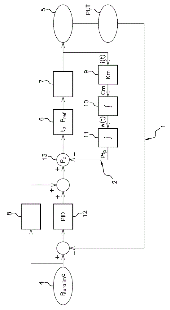
[0046]The schematic diagram of the sole figure defines the operation of the system for the control of the electric actuator 7 of the regulating valve (not shown) which allows the exhaust gas of the internal combustion engine (not shown) to flow from the turbine of the turbocharger The fluid supply circuit is diverted, and the turbocharger is designed to compress the air introduced into the internal combustion engine into the new gas circuit. The electric actuator 7 is controlled in a known manner by means of an H-bridge (not shown) in order to allow the valve in its closing direction and Shift in its opening direction. The system shown comprises two feedback loops 1, 2 as disclosed below.
[0047] Set boost pressure P suralim c present at the inlet 4 of the system, said set boost pressure is demanded in a known manner by the electronic control unit of the engine (not shown, hereinafter referred to as ECU), which is the ratio of the engine torque on the driver's part A funct...
PUM
 Abstract
Description
Claims
Application Information
 - R&D
- Intellectual Property
- Life Sciences
- Materials
- Tech Scout
- Unparalleled Data Quality
- Higher Quality Content
- 60% Fewer Hallucinations
Browse by: Latest US Patents, China's latest patents, Technical Efficacy Thesaurus, Application Domain, Technology Topic, Popular Technical Reports.
© 2025 PatSnap. All rights reserved.Legal|Privacy policy|Modern Slavery Act Transparency Statement|Sitemap|About US| Contact US: help@patsnap.com