Closed mechanical seal pump effect ring and shaft seal flushing system with the pump effect ring

A technology for mechanical sealing and flushing systems, applied in mechanical equipment, non-variable volume pumps, components of pumping devices for elastic fluids, etc. Achieve the effect of increasing the flow area, lengthening the fluid flow path, and improving the performance of the mechanical seal

Active Publication Date: 2017-03-15
天津长瑞大通流体控制系统有限公司
View PDF7 Cites 0 Cited by
  • Summary
  • Abstract
  • Description
  • Claims
  • Application Information

AI Technical Summary

Problems solved by technology

[0006] 3. Due to the short distance that the fluid passes in the sealing cavity, that is to say, the path is short, only a small part of the liquid in the part where the fluid passes participates in the flow, and most of the liquid is always in a static state. The two sets of mechanical seal friction pairs are the most needed. Cooling place, but the nearby cooling liquid is always in a relatively static state, which is quite unfavorable for mechanical seals
[0008] 5. In order to produce an effective head, reduce backflow and improve driving efficiency, the maximum outer diameter of the rotating pump effect ring should be as close as possible to the inner wall of the stationary cavity. As a result, the part of the liquid between the moving part and the stationary part Under a great shearing force, it not only consumes power, generates excess heat, but even destroys the molecular structure of the liquid and affects the physical and chemical stability of the liquid.
[0009] 6. Due to the small gap between the inner walls of the stationary cavity of the rotating pump effect ring, interference often occurs and the mechanical seal fails
[0014] 11. It is impossible to effectively adjust the flow rate and pressure difference of the circulating fluid by changing the geometric parameters of the pump effect ring
Therefore, the thermal balance cannot be actively adjusted.
[0015] 12. It is difficult to achieve the effect of the pump with low speed (n<1000rad / min)

Method used


Image

  • Closed mechanical seal pump effect ring and shaft seal flushing system with the pump effect ring
  • Closed mechanical seal pump effect ring and shaft seal flushing system with the pump effect ring
  • Closed mechanical seal pump effect ring and shaft seal flushing system with the pump effect ring

Examples


Embodiment Construction

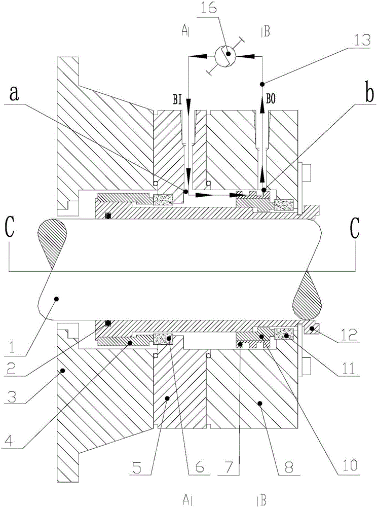
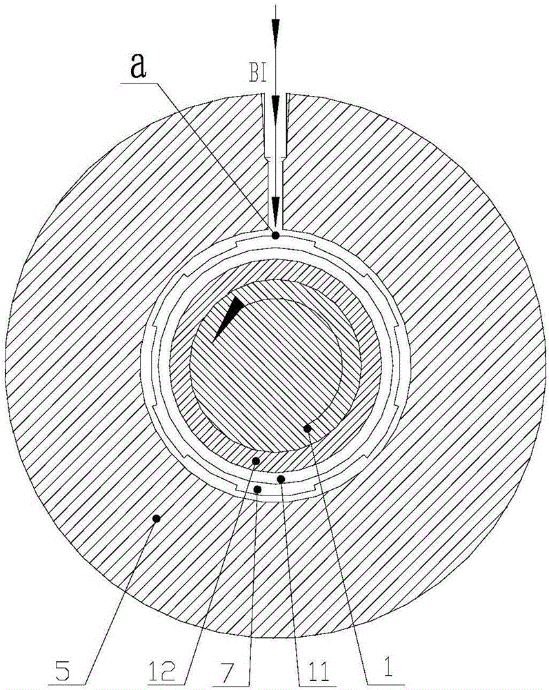
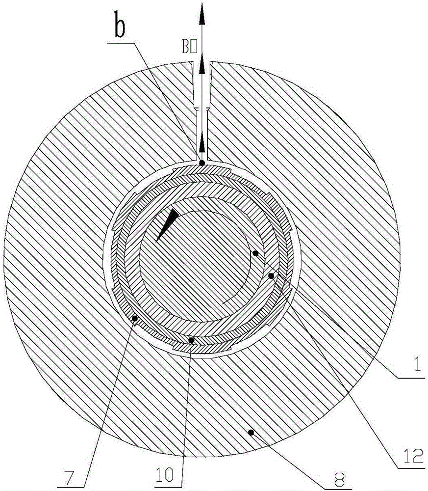
[0099] The closed mechanical seal pump effect ring and the shaft seal flushing system with the pump effect ring of the present invention will be described in detail below with reference to the embodiments and the accompanying drawings.

[0100] The closed mechanical seal pump effect ring and the shaft seal flushing system with the pump effect ring of the present invention are firstly a pump effect ring with a closed channel and can provide reliable and stable head and flow rate fluid, and the pump effect ring can not only provide stable acceleration for the fluid , and increase the acceleration distance of the liquid, and make the directionality of the fluid flow velocity strong to reduce useless work. It can not only allow most of the liquid in the sealed cavity to participate in the flow, but also lengthen the fluid flow path and increase the flow area. In API682, the shaft seal system standard for pumps, 2CW-CW cartridge double-contact wet seal with buffer fluid and 3CW-FB ...


PUM


Abstract

Disclosed is a closed type mechanical sealing pump efficiency ring. The pump efficiency ring is provided with annular left side plate (701) of the pump efficiency ring and right side plate (702) of the pump efficiency ring mutually arranged in parallel; inner rings of the left side plate (701) of the pump efficiency ring and the right side plate (702) of the pump efficiency ring are sheathed on a peripheral surface of a shaft sleeve (12) of a centrifugal pump, peripheries of the left side plate (701) of the pump efficiency ring and the right side plate (702) of the pump efficiency ring are linked to a sealing gland of the centrifugal pump and have gaps, a plurality of blades (703) rotationally arranged in a radiation state is arranged between the left side plate (701) of the pump efficiency ring and the right side plate (702) of the pump efficiency ring, the plurality of blades (703) is in vertical arrangement with the left side plate (701) of the pump efficiency ring and the right side plate (702) of the pump efficiency ring, end openings formed by closing-in ends of the plurality of blades (703) in the radiation state correspond to a liquid outlet of the shaft sleeve (12), and end openings formed by radiating ends of the plurality of blades (703) in the radiation state correspond to a liquid inlet formed on a liquid outlet passage on the sealing gland. Also disclosed is a shaft seal flushing system having the pump efficiency ring. The pump efficiency ring enables the majority of a liquid in a sealing cavity to flow, increases an accelerated distance of the liquid and lengthens a flowing path of the liquid, thereby enlarging the orifice area.

Description

technical field [0001] The invention relates to a shaft seal flushing system of a centrifugal pump. In particular, it relates to a closed mechanical seal pump effect ring and a shaft seal flushing system with the pump effect ring. Background technique [0002] In the API682 standard appendix D of the centrifugal pump and rotor pump shaft seal system, the standard seal flushing plan 52, 53A, 53B, 53C internal liquid circulation power is provided by the pump effect ring, such as figure 1 Shown prior art. figure 1 , figure 2 , image 3 Schematic diagram showing the flushing system and internal structure of the prior art 2CW-CW cartridge double-contact wet seal with buffer fluid and 3CW-FB cartridge double-contact wet seal with barrier fluid facing back configuration. Figure 4 A schematic diagram showing the flushing system and internal structure of the prior art 3CW-BB with the back-to-back configuration of the cartridge double-contact wet seal (1.2 in API682). After the...

Claims


Application Information

Patent Timeline
Patent Type & Authority Patents(China)
IPC IPC(8): F04D29/12F04D29/70F04D29/58
CPCF04D29/12F04D29/58F04D29/70
Inventor 邢宇邢天宜
Owner 天津长瑞大通流体控制系统有限公司
Why Eureka
Try Eureka