Method and device for detecting and handling load faults of power amplifier

A coping method and fault technology, applied in the direction of measuring devices, measuring electricity, measuring electrical variables, etc., can solve problems such as damage to power tubes

Inactive Publication Date: 2015-06-10
广州播博科技有限公司
View PDF9 Cites 21 Cited by
  • Summary
  • Abstract
  • Description
  • Claims
  • Application Information

AI Technical Summary

Problems solved by technology

The problem is that the power amplifier will continue to try to start when the fault is not eliminated. As we all know, under fault conditions, the current flowing through the power tube greatly exceeds the current used when playing music normally. , will damage the power tube

Method used


Image

  • Method and device for detecting and handling load faults of power amplifier
  • Method and device for detecting and handling load faults of power amplifier

Examples


Embodiment

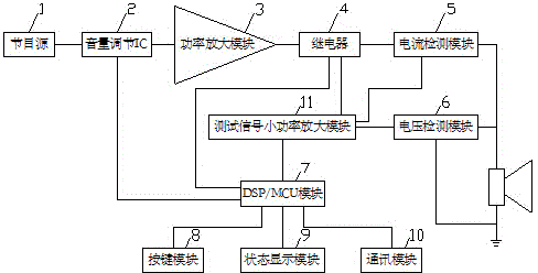
[0026] like figure 1 As shown, a power amplifier load failure detection and response device includes:

[0027] Current detection module 5: use resistance serial connection method to sample or use current transformer to detect the current of the power amplifier load circuit, and the current signal is supplied to the DSP / MCU module;

[0028] Voltage detection module 6: use the principle of voltage division of resistors or voltage reduction of transformers to supply the DSP / MCU module after the voltage signal of the power amplifier load circuit is reduced;

[0029] DSP / MCU module 7: use the DSP chip with MCU function or the MCU chip with A / D input port to receive the signal sent by the current detection module 5 and the voltage detection module 6, and obtain the impedance curve data through internal calculation, power data to obtain fault information.

[0030] As an improvement to the solution of the above embodiment, it also includes a button module 8, which is electrically co...

Embodiment 2

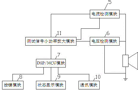
[0038] like figure 1 , 2 As shown, the power amplifier load circuit in embodiment 2 is the same as embodiment 1, and as an improvement of the above-mentioned embodiment 1 scheme, it also includes a test signal generator, a test signal low power amplification module 11 and a switch; the test signal generator Integrated in the DSP / MCU module 7, the test signal sent is a 20Hz~20KHz frequency sweep signal or a ladder signal, and the test signal low-power amplification module 11 performs a low-power test signal on the 20Hz~20KHz audio test signal sent by the DSP / MCU module 7. Amplified, sent to the load line as a test signal source, and electrically connected to the power amplifier load circuit through the test signal low-power amplification module 11 and the switch.

[0039] If the full-frequency test is selected, the DSP / MCU module 7 generates a 20Hz~20KHz test signal. After the test signal is passed through the low-power amplification module 11, the relay 4 is used as a switch ...


PUM


Abstract

The invention discloses a method for detecting and handling load faults of a power amplifier. The method comprises the following steps of providing real-time parameters through current and voltage detection, thereby calculating to obtain online power and impedance curve data as the basis of reducing output power or short-circuit protection states. The invention further discloses a device for detecting and handling load faults of the power amplifier, and the device comprises a current detecting module, a voltage detecting module, and a DSP/MCU (digital signal processor/micro controller unit) module. According to the method and the device, when a sound system is installed, and the power amplifier can distinguish whether the load impedance is normal and performs corresponding adjustment, thereby ensuring that the load on the circuit meets the output impedance of the power amplifier; when the sound system is normally used, load power and impedance of the power amplifier are monitored and automatically treated when the output circuit of the power amplifier or a loudspeaker emerges questions. According to the method and the device, the load is automatically disconnected in a short-circuit state and automatically connected after the short circuit is eliminated, the output power is automatically reduced in overload so that the sound cannot be interrupted and the output power can be automatically recovered after the overload is eliminated.

Description

technical field [0001] The invention relates to a detection and response method and device for power amplifier load faults. Background technique [0002] The output lines of audio power amplifiers (referred to as power amplifiers) sometimes have artificial or non-artificial short-circuits, or are connected to the power grid, or are blown off by strong winds, or have speaker damage. Therefore, almost all power amplifiers on the market have load short-circuit protection. function and overload protection function. The existing power amplifier products have a shortcoming. After entering the protection state, even if the fault is eliminated, it cannot be automatically restored, and the power amplifier needs to be restarted manually. This is unacceptable in many important occasions, such as in unattended computer rooms. of. In response to this, there are a small number of power amplifiers on the market that are delayed after entering the protection and start automatically. The ...

Claims


Application Information

Patent Timeline
Patent Type & Authority Applications(China)
IPC IPC(8): G01R31/02
Inventor 王齐祥
Owner 广州播博科技有限公司
Why Eureka
Try Eureka