

Self-adaptive sliding method of displacement field of digital image relevant method based on kernel function
A digital image and kernel function technology, applied in image enhancement, image data processing, instruments, etc., can solve problems such as manual adjustment of algorithms, hindering practical applications, etc.
- Summary
- Abstract
- Description
- Claims
- Application Information
AI Technical Summary
Problems solved by technology
Method used
Image

Examples
Embodiment 1
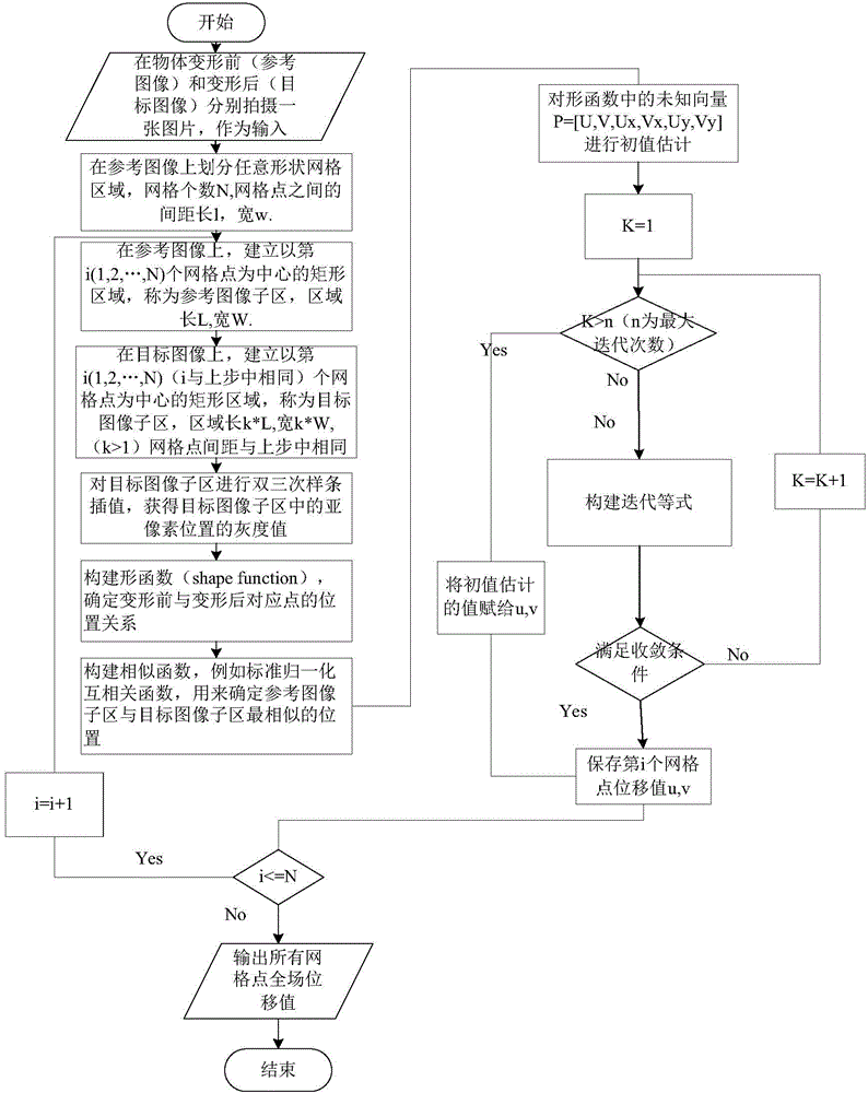
[0151] The displacement field adaptive smoothing method of digital image correlation method based on kernel function includes the following steps: 1) Collect the images before and after the deformation of the object, the image before the deformation is the reference image, and the image after the deformation is the target image;
[0152] 2), select the region of interest S on the reference image 1 , Area of interest S 1 Is the reference image sub-region; obtained by the following steps: divide the first grid on the reference image, the number of the first grid is M rows×N columns, and the length and width of the reference image The distances between the two are l and w, and the interest area S with the i-th first grid as the center is established on the reference image 1 , Area of interest S 1 It is a reference image sub-region, and the length and width of the reference image sub-region are L and W respectively, where a=1, 2, 3..., M×N. It is simple and convenient to select th...
Embodiment 2
[0252] Example 2: Non-uniform deformation
[0253] The actual deformation is often non-uniform. In order to evaluate the effect under non-uniform deformation conditions, the sine function u(x,y)=Asin(2πx / p) is selected to describe the deformation of the structure, where the amplitude A is 0.1 and the period parameter p is 200, and the rest of the deformation parameters are the same as in Example 1. The calculation result is as Figure 14 with Figure 15 As shown, the left side is the strain field calculated by the difference of the displacement field data output by the traditional DIC, and the right side is the strain field data calculated by the smooth DIC. It can be seen that the strain field calculated by the traditional DIC method is relatively rough and is more seriously affected by the noise of the displacement field. After smoothing the displacement field with the method in this paper, the strain field data obtained is smooth and closer to the theoretical value. The RMS ...
Embodiment 3
[0256] Example 3: Hole experiment:
[0257] See Figure 16 , 17 As shown in and 18, in order to further verify the practicability of this method, the actual deformation of the specimen will be processed here. The experimental specimen is a specimen with holes, the schematic diagram is as Figure 18 As shown, the specimen number is BD1W2L3, where B represents steel, D=1 is the hole diameter, W=2 is the horizontal hole interval, and L=3 is the longitudinal hole interval. The total length of the specimen is 200mm and the width is 20mm. During the test, an industrial AVT camera, model F-125B / C, was used to collect images before and after deformation.
[0258] The strain contours of traditional DIC and smooth DIC output are in Figure 19 , 20 , 21 and 22. By comparison, it can be seen that the overall law of the calculation results of the two methods is consistent, that is, the locations of stress concentration coincide. However, the results of the traditional DIC calculation are dist...
PUM
 Abstract
Description
Claims
Application Information