Equipment for the mechanical separation of oil and bitumen from gas condensates

A condensate and oil separation technology, applied in liquid separation, gas processing condensate, separation methods, etc., can solve the problems of volume space and cost of slow gas condensate

Active Publication Date: 2019-04-26
LAIR LIQUIDE SA POUR LETUDE & LEXPLOITATION DES PROCEDES GEORGES CLAUDE
View PDF6 Cites 0 Cited by
  • Summary
  • Abstract
  • Description
  • Claims
  • Application Information

AI Technical Summary

Problems solved by technology

However, the above-mentioned settling tanks are not very suitable for separating smaller bitumen particles and oil droplets, since the separation process proceeds very slowly and requires the gas condensate to stay in these settling tanks for a long time and thus requires the equipment Very large volume and a lot of space and cost

Method used


Image

  • Equipment for the mechanical separation of oil and bitumen from gas condensates
  • Equipment for the mechanical separation of oil and bitumen from gas condensates

Examples


Embodiment Construction

[0035] The accompanying drawings show:

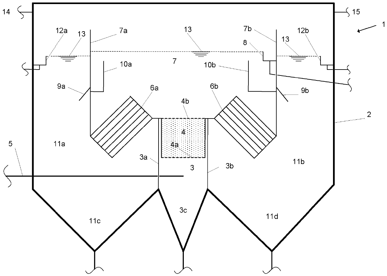
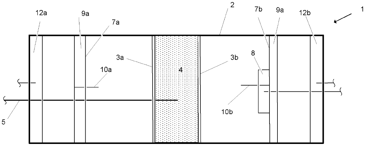
[0036] A device 1 comprising an outer tank 2 having a rectangular cross-section and internal fittings present therein, the device 1 will be described in detail hereinafter;

[0037] Partitions 3a, 3b forming an inlet chamber 3 into which gas condensate to be cleaned is fed via a feed conduit 5;

[0038] a coalescent tank 4, filled with metallurgical coke, and the upper side 4b and the lower side 4a of the coalescent tank 4 are perforated;

[0039] Parallel or corrugated plate separators 6a, 6b;

[0040] Partitions 7a, 7b which separate the oil separation chamber 7 from the remaining tank space;

[0041] Oil collecting plates 9a, 9b mounted on the partitions 7a, 7b with one long side;

[0042] Conduits 10a, 10b, which guide the oil collected under the oil collecting plate, pass through openings, not shown in the figures, in the corresponding partitions into the oil separation chamber 7 slightly below the liquid level 13;

[0043] an o...


PUM


Abstract

An apparatus for the mechanical separation of oil and tar from gas condensate, which comprises a tank which is equipped with a container to be traversed by gas condensate, which contains metallurgical coke, and with parallel plate separators, wherein partitions divide the container volume into compartments in which the oil and the tar settle from the gas condensate under the influence of gravity.

Description

technical field [0001] The invention relates to a plant for the mechanical separation of oil and bitumen from gas condensate, comprising a tank equipped with a vessel to be traversed by the gas condensate, the vessel comprising a coalescing aid, and The tank is equipped with a parallel plate separator in which partitions divide the vessel volume into chambers in which oil and tar settle under the influence of gravity from the gas condensate. Background technique [0002] Solid fuels such as coal, coke or other carbonaceous fuels are gasified by means of a fixed bed pressure gasification reactor at high temperature and in most cases under overpressure with steam and oxygen as the gasification medium to obtain A synthesis gas comprising carbon monoxide and hydrogen, wherein solid ash is obtained, which is discharged from the reactor via an ash discharge furnace, which in many cases is formed as a rotary kiln. Reactors of this type are often also referred to as FBDB (=fixed be...

Claims


Application Information

Patent Timeline
Patent Type & Authority Patents(China)
IPC IPC(8): B01D17/025B01D17/028
CPCC10K1/001B01D21/0012B01D21/0045C10J3/02C10K1/046
Inventor 埃哈德·莱瑟弗雷德里克·朱达斯
Owner LAIR LIQUIDE SA POUR LETUDE & LEXPLOITATION DES PROCEDES GEORGES CLAUDE
Why Eureka
Try Eureka