Chamber cleaning device and control method thereof
A technology of cleaning device and control method, applied in the field of chamber cleaning device and its control, capable of solving problems such as low cleaning efficiency and changes in environmental factors
- Summary
- Abstract
- Description
- Claims
- Application Information
AI Technical Summary
Problems solved by technology
Method used
Image
Examples
Embodiment 1
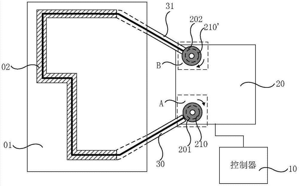
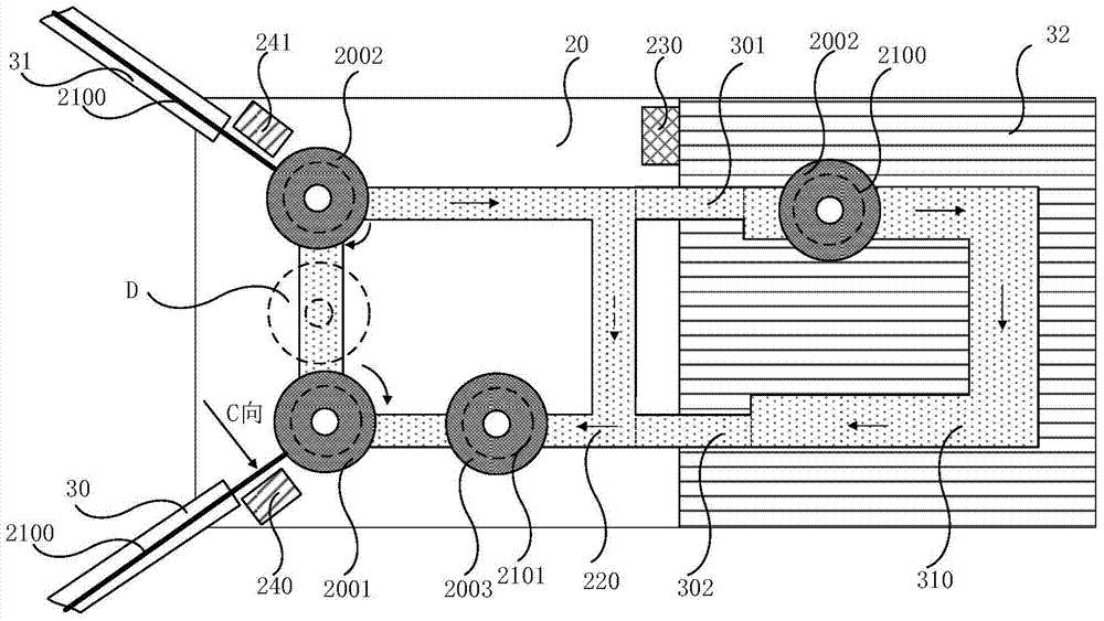
[0046] Such as figure 2 As shown, the supply device 20 may further include an annular supply guide rail 220 on which the first station A and the second station B are arranged. The reels ( 201 and 202 ) are installed on the supply guide rail 220 , and can move along the supply guide rail 220 under the control of the controller 10 . In this way, the supply guide rail 220 can provide a movement path for realizing the automatic replacement of the reel.
[0047] In order to realize automatic replacement of reels, the supply device 20 may further include a first replacement unit 240 and a second replacement unit 241 .
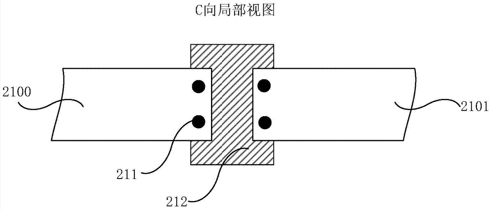
[0048] Specifically, the first replacement unit 240 can be arranged between the delivery inlet 30 and the first station A, and is used to connect the ends and the starting ends of two adjacent rolls of cleaning cloth 210;
[0049] The second replacement unit 241 is arranged between the delivery outlet 31 and the second station B, and is used to separate the end an...
Embodiment 2
[0070] Such as figure 2 As shown, the chamber cleaning device may further include a reduction device 32 to realize the reduction treatment of the cleaning cloth 210 .
[0071] Specifically, a restoring guide rail 310 may be provided in the restoring device 32 . The reduction guide rail 310 is connected to the supply guide rail 220 through a reduction inlet 301 and a reduction outlet 302 . In this way, the restoring device 32 can restore the cleaned cleaning cloth 210 so that it can be reused. The specific restoration process may be cleaning and drying the cleaning cloth 210 . Alternatively, when the cleaning cloth 210 is an activated carbon fiber cloth, the activated carbon fiber cloth may be reduced by a desorption method. The specific desorption methods may include: high temperature desorption, decompression desorption, flushing desorption, displacement desorption, magnetization desorption, ultrasonic desorption and so on.
[0072] In addition, the chamber cleaning device...
Embodiment 3
[0090] The cleaning track 02, as Figure 4 As shown, at least one position adjuster 40 may be included. The position regulators 40 may be distributed inside the chamber 01 along a preset track.
[0091] Wherein, the aforementioned preset track refers to the running track of the cleaning cloth 210 preset in the chamber. The design principle is that the cleaning cloth 210 cannot affect the normal operation of other devices in the chamber 01 while it is running along the preset trajectory. For example, when the chamber 01 is a working chamber of an exposure machine, an object stage for carrying a substrate to be exposed, a light source for exposing, and a mask plate are arranged in the working chamber of the exposure machine. Therefore, the above-mentioned running track needs to bypass the exposure working parts and working areas such as the stage, the light source, and the mask plate, so as to avoid the impact of the cleaning cloth 210 on the substrate, The mask plate or the ...
PUM
 Abstract
Description
Claims
Application Information
 - R&D
- Intellectual Property
- Life Sciences
- Materials
- Tech Scout
- Unparalleled Data Quality
- Higher Quality Content
- 60% Fewer Hallucinations
Browse by: Latest US Patents, China's latest patents, Technical Efficacy Thesaurus, Application Domain, Technology Topic, Popular Technical Reports.
© 2025 PatSnap. All rights reserved.Legal|Privacy policy|Modern Slavery Act Transparency Statement|Sitemap|About US| Contact US: help@patsnap.com


