Composite wear-resistant part preparation method

A technology of composite wear-resistant parts and wear-resistant parts, which is applied in the field of preparation of ball mill liners and composite wear-resistant parts. problems, to achieve the effect of facilitating mechanized operation, simplifying the production process and improving the service life of the product

Active Publication Date: 2015-06-17
GUANGDONG INST OF NEW MATERIALS
View PDF14 Cites 14 Cited by
  • Summary
  • Abstract
  • Description
  • Claims
  • Application Information

AI Technical Summary

Problems solved by technology

[0005] 1. The process of making ceramic preforms from ceramic particles is cumbersome, and the molds are put into the sintering furnace for sintering together, which consumes financial resources, manpower and energy;
[0006] 2. The ceramic prefabricated body is too simple in the form of columns, strips, blocks or honeycombs, and the actual product working surface is complex in configuration and cannot meet the demand;
[0007] 3. The distance between the prefabricated bodies is at least 10mm, which leads to the reservation of a large number of non-wear-resistant areas on the wear surface, resulting in a short service life of the wear-resistant parts

Method used


Image

  • Composite wear-resistant part preparation method
  • Composite wear-resistant part preparation method
  • Composite wear-resistant part preparation method

Examples


preparation example Construction

[0032] The preparation method of the composite wear-resistant part of the present invention comprises the following steps:

[0033] 1) Determine the wear surface and failure mode under the working conditions of the wear-resistant parts, and design the configuration of the ceramic reinforcement: the thickness of the configuration is 3-80mm, and the configuration can be strip-shaped, plate-shaped or porous, etc. It is necessary to ensure the instant ceramic The absolute distance from any point in the reinforcing body to the molten metal is less than 10mm;

[0034] 2) Design and manufacture molds according to the designed ceramic reinforcement configuration;

[0035] 3) Surface nickel-plated ceramic particles with a particle size of 0.1-7mm;

[0036] 4) Mix the treated ceramic particles with a binder with a weight percentage of 0.5-2%, fill them in a mold, and adopt a method of warm pressing to make a ceramic reinforcement green body with a certain strength;

[0037] 5) Remove ...

Embodiment 1

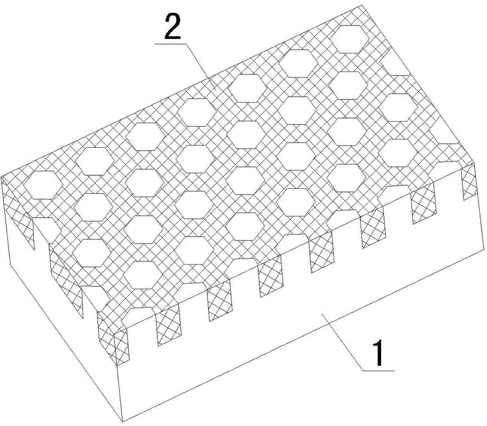
[0042] 1) Determine the wear surface and failure mode of the liner of the ball mill, and design the configuration of the ceramic reinforcement, such as figure 1 As shown, the thickness of the configuration is 40mm, and the configuration is porous (hexagonal honeycomb holes). It is necessary to ensure that the absolute distance from any point in the ceramic reinforcement to the molten metal at the moment of casting is less than 10mm;

[0043] 2) Design and manufacture molds according to the designed ceramic reinforcement configuration;

[0044] 3) Surface nickel-plated ceramic particles with a particle size of 4-7 mm;

[0045] 4) Mix the processed ceramic particles with 2% by weight binder, fill them in the mold, and use warm pressing to make a ceramic reinforcement green body with a certain strength;

[0046] 5) Remove the mold, put it into the atmosphere furnace for degreasing and sintering, and obtain a ceramic reinforcement with three-dimensional multi-scale interconnected...

Embodiment 2

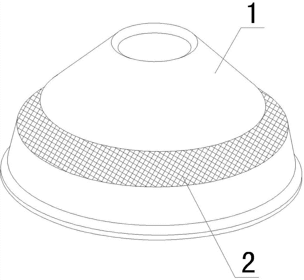
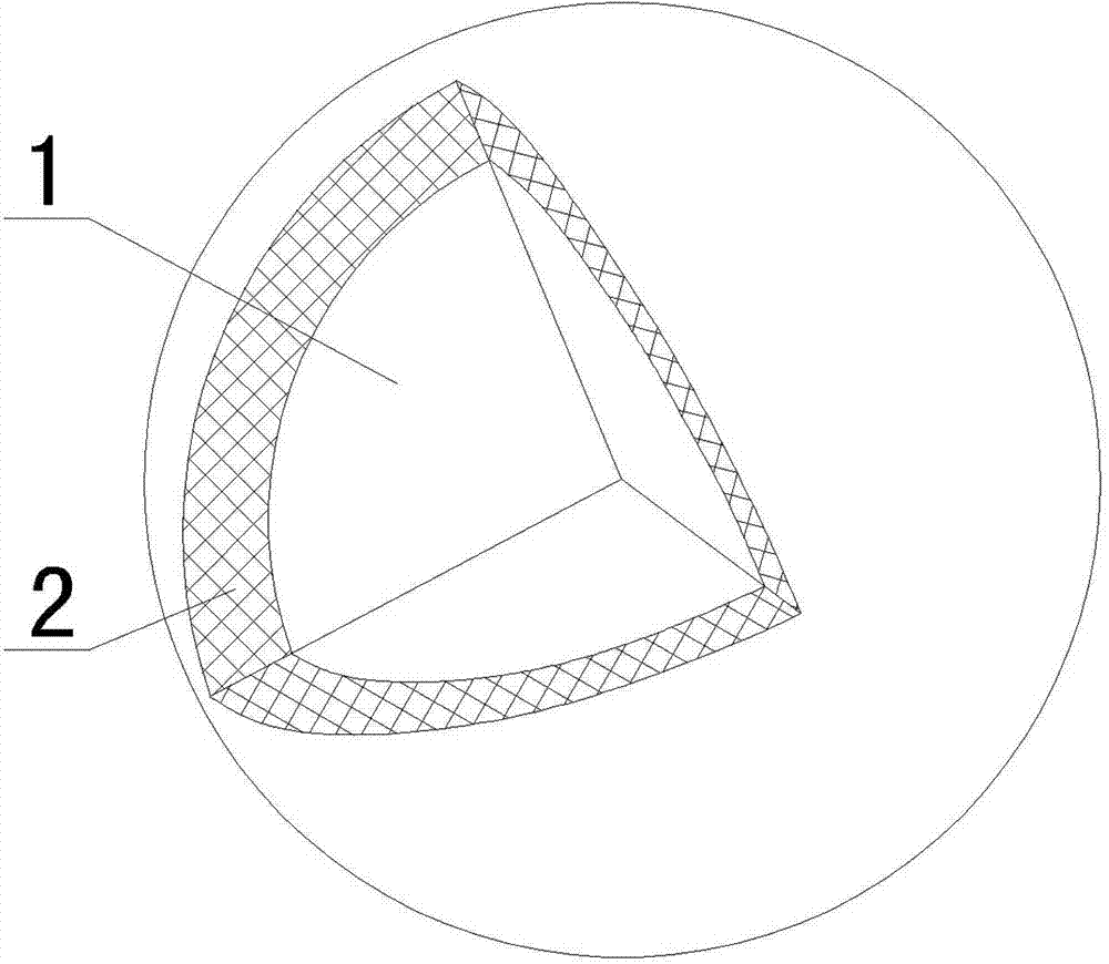
[0051] 1) Determine the wear surface and failure mode under the working condition of the broken wall of the crusher, such as figure 2 As shown, the ceramic reinforcement is designed to be strip-shaped, and the thickness of the configuration is 60mm. It is necessary to ensure that the absolute distance from any point in the ceramic reinforcement to the molten metal at the moment of casting is less than 10mm;

[0052] 2) Design and manufacture molds according to the designed ceramic reinforcement configuration;

[0053] 3) Surface nickel-plated ceramic particles with a particle size of 0.5-3mm;

[0054] 4) Mix the treated ceramic particles with 0.8% by weight of binder, fill them in the mold, and use the method of warm pressing to make a ceramic reinforcement green body with a certain strength;

[0055] 5) Remove the mold, put it into the atmosphere furnace for degreasing and sintering, and obtain a ceramic reinforcement with three-dimensional multi-scale interconnected pores;...


PUM

PropertyMeasurementUnit
thicknessaaaaaaaaaa
particle diameteraaaaaaaaaa

Abstract

The invention provides a composite wear-resistant part preparation method. The composite wear-resistant part preparation method comprises the following steps that firstly, the wear surface and the failure mode of a wear-resistant part under working condition are determined, and a ceramic reinforcement configuration is designed, wherein the thickness of the ceramic reinforcement configuration ranges from 3 mm to 80 mm, and the configuration can be in a bar shape, a plate shape or a porous shape to guarantee that the absolute distance from an arbitrary point in ceramic reinforcement to molten metal is smaller than 10mm at the moment of casting; secondly, the ceramic reinforcement is prepared; thirdly, a metallic matrix is cast to enable the ceramic reinforcement and the metallic matrix to be mutually combined to form a composite wear-resistant part, ceramic particles forming the ceramic reinforcement are evenly distributed on the wear surface of the wear-resistant part, and the ceramic particles are firmly coated by the metallic matrix. According to the composite wear-resistant part preparation method, the production technology is more simplified, the mechanized operation is facilitated, the ceramic particles are enabled to be evenly distributed on the wear surface of the wear-resistant part, and therefore the service life of the product is effectively prolonged.

Description

technical field [0001] The invention belongs to the technical field of manufacturing iron-based composite materials, and in particular relates to a method for preparing composite wear-resistant parts such as ball mill lining boards, grinding balls, and crusher broken walls used for ball milling and crushing materials in the fields of mines, cement, machinery, etc. . Background technique [0002] Wear-resistant materials are widely used in key components of equipment in metallurgy, electric power, machinery, building materials, mines, automobiles, high-speed trains, etc., with a wide coverage and large consumption. However, the wear-resistant materials widely used at home and abroad are still at the level of traditional steel materials In terms of production, there are mainly high-chromium cast iron, high-manganese steel, nodular cast iron, alloy steel, etc. The wear resistance and toughness are mutually restricted, the consumption is large, and the safety is poor, which has ...

Claims


Application Information

Patent Timeline
Patent Type & Authority Applications(China)
IPC IPC(8): B22D19/08
Inventor 王娟郑开宏王秀连周楠王海艳
Owner GUANGDONG INST OF NEW MATERIALS
Why Eureka
Try Eureka