Supporting device and machining precision improving method for thin-wall part

A support device and processing precision technology, applied in positioning devices, metal processing equipment, metal processing machinery parts, etc., can solve problems such as influence, large image fluctuations, and influence parameter selection

Inactive Publication Date: 2015-06-17
BEIJING INSTITUTE OF TECHNOLOGYGY
View PDF8 Cites 11 Cited by
  • Summary
  • Abstract
  • Description
  • Claims
  • Application Information

AI Technical Summary

Problems solved by technology

[0002] In the field of mechanical manufacturing, the most direct way to evaluate the machining results is the final surface quality of the workpiece, and the regenerative chatter during the machining process has the greatest impact on the final machining results (especially for thin-walled parts, which are usually processed by milling). The formation theory and suppression method of vibration are basically mature. At present, when performing theoretical calculations, it is mostly assumed that the X direction does not affect the Y direction (radial depth of cut), that is, the two are independent. In the actual processing process, there is often coupling between the two directions. phenomenon, which affects the final simulation prediction results; and in the milling process, when the radial immersion is determined, it is often considered that the cut-in angle and the cut-out angle are fixed in the theoretical calculation, which affects the subsequent simulation. In addition, when the calculation of the frequency response

Method used


Image

  • Supporting device and machining precision improving method for thin-wall part
  • Supporting device and machining precision improving method for thin-wall part
  • Supporting device and machining precision improving method for thin-wall part

Examples


Embodiment Construction

[0057] One, the embodiment of device of the present invention:

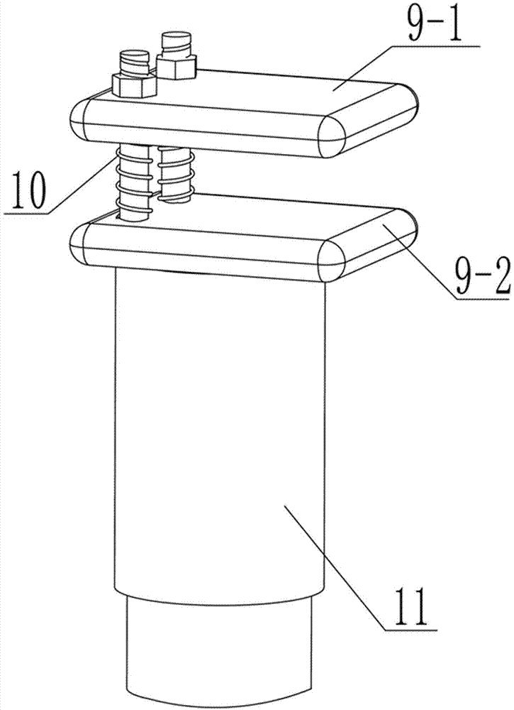
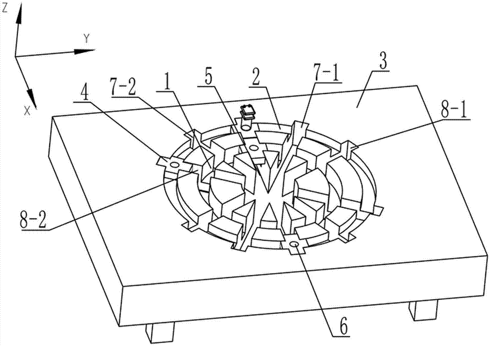
[0058] Such as figure 1 , 2 As shown, a support device for thin-walled parts includes a support platform 3, a first loop 1, a second loop 2, an X-direction slide 5, a matching buckle 4 with a through hole 6, and a first slide 7 -1, the second slideway 7-2, the third slideway 8-1, the fourth slideway 8-2 and the supporting mechanism for fixing and supporting the thin-walled parts; the first loop 1 and the second loop 2 concentrically and sequentially arranged on the support platform 3, the X-direction slideway 5 is arranged on the support platform 3 and passes through the center of the first loop 1 and the second loop 2, the first slideway 7-1 and The second slideway 7-2 is symmetrically arranged on both sides of the X-direction slideway 5, the third slideway 8-1 and the fourth slideway 8-2 are symmetrically arranged on both sides of the X-direction slideway 5, and the matching buckle 4 Set at the intersection ...


PUM


Abstract

The invention relates to the field of advanced manufacturing, in particular to a supporting device and a machining precision improving method for a thin-wall part. Matching buckles are matched with ring ways and slide ways so that supporting postures of different space shapes can be completed on a supporting table, a thin-wall part can be fixedly supported effectively, and more precise modal parameters can be obtained through clamping conducted through the supporting device. Under the circumstance that boundary limiting conditions such as the cut-in angle, the cut-out angle and the cutting thickness are considered sufficiently, a numerical integration method is used for iterative operation, a vibration displacement simulating diagram is obtained by subdividing the rotating speed of a main shaft and the axial cutting depth within a certain range, a milling stability diagram is finally obtained, simulation precision is improved, and machining quality is improved.

Description

technical field [0001] The invention relates to the field of advanced manufacturing, in particular to a support device for thin-walled parts and a method for improving machining accuracy thereof. Background technique [0002] In the field of mechanical manufacturing, the most direct way to evaluate the machining results is the final surface quality of the workpiece, and the regenerative chatter during the machining process has the greatest impact on the final machining results (especially for thin-walled parts, which are usually processed by milling). The formation theory and suppression method of vibration are basically mature. At present, when performing theoretical calculations, it is mostly assumed that the X direction does not affect the Y direction (radial depth of cut), that is, the two are independent. In the actual processing process, there is often coupling between the two directions. phenomenon, which affects the final simulation prediction results; and in the mil...

Claims


Application Information

Patent Timeline
IPC IPC(8): B23Q3/06G06F19/00
CPCB23C3/00B23C2270/08B23Q3/065G16Z99/00
Inventor 刘志兵王东前刘彪闫正虎王西彬赵倩吕维维
Owner BEIJING INSTITUTE OF TECHNOLOGYGY
Why Eureka
Try Eureka