
A chip removal device

A technology of equipment and transmission track, which is applied in the field of plate processing, can solve the problems of low efficiency of manual chip removal and cannot adapt to the streamlined production of processing workshops, and achieve the effects of improving plate processing efficiency, improving dust removal efficiency, and reducing dust removal pressure

Active Publication Date: 2016-06-22
DUOWEI UNION GRP
View PDF6 Cites 0 Cited by
  • Summary
  • Abstract
  • Description
  • Claims
  • Application Information

AI Technical Summary

Problems solved by technology

[0005] The technical problem to be solved by the present invention is to provide a chip removal equipment suitable for plate processing, which solves the problem that the traditional manual chip removal operation has low efficiency and cannot adapt to the streamlined production of the processing workshop

Method used


Image

  • A chip removal device
  • A chip removal device
  • A chip removal device

Examples


Embodiment Construction

[0033] The implementation of the present invention will be described in detail below with reference to the drawings and examples, so as to fully understand and implement the implementation process of how to use technical means to solve technical problems and achieve technical effects in the present invention.

[0034] Certain terms are used, for example, in the description and claims to refer to particular components. Those skilled in the art should understand that hardware manufacturers may use different terms to refer to the same component. The specification and claims do not use the difference in name as a way to distinguish components, but use the difference in function of components as a criterion for distinguishing. As mentioned throughout the specification and claims, "comprising" is an open term, so it should be interpreted as "including but not limited to". "Approximately" means that within an acceptable error range, those skilled in the art can solve the technical p...


PUM


Abstract

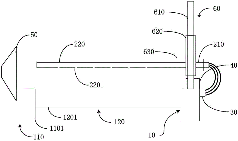
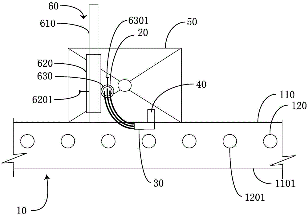
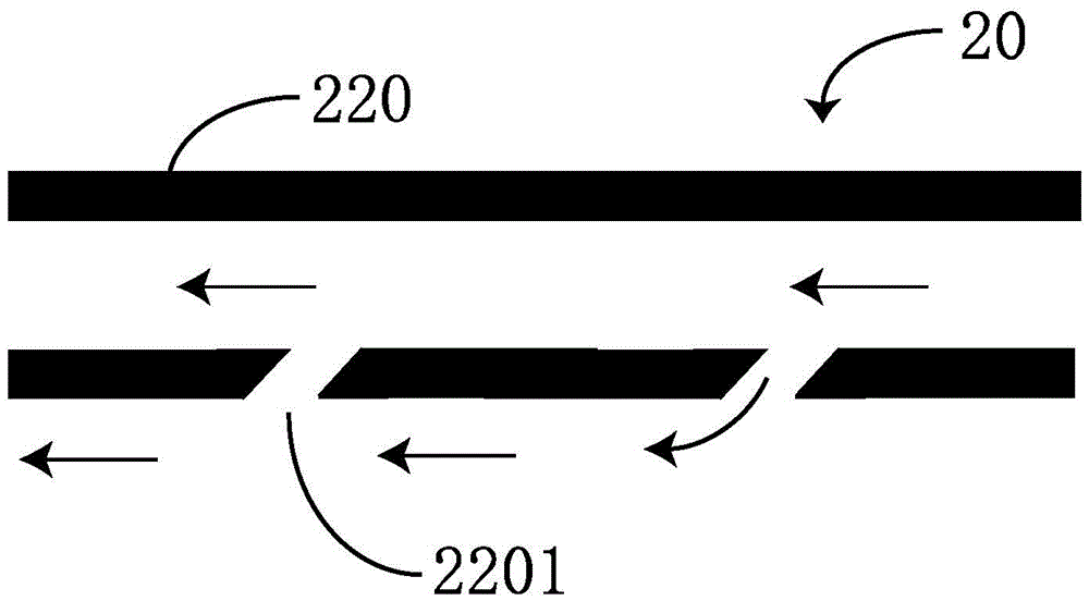
The invention discloses a scrap removing device which is applicable to plate machining. The scrap removing device comprises a conveying track, an air blow pipe, an air supply device and a light sensing device. The conveying track is used for conveying plates. The side, facing the conveying track, of the air blow pipe is provided with a plurality of air outlet holes. The air supply device is connected to the air blow pipe and used for supplying air to the air blow pipe. The light sensing device is used for projecting light rays along a short side. When the plates shield the projected light rays, the light sensing device senses corresponding reflected light rays and drives the air supply device to supply the air to the air blow pipe according to the sensing result so that the air can be blown to the surfaces of the plates through the air outlet holes and can blow away impurities on the surfaces of the plates. By the adoption of the scrap removing device, the problem that when a traditional manual scrap removing method is adopted, the operating efficiency is low, and the method can not adapt to streamlined production in processing workshops, labor is saved, the dedusting efficiency is improved, and the dedusting pressure of big environments of the processing workshops is lowered.

Description

technical field [0001] The invention relates to the field of plate processing, in particular to a chip removal device suitable for plate processing. Background technique [0002] In the field of modern architecture, wall panels for thermal insulation are often used in the construction of some large-scale factories. The main core materials are rock wool, glass wool, and polyurethane, which have been widely used due to their good thermal insulation properties. Although most of the walls using these boards are non-load-bearing walls, rock wool, glass wool, and polyurethane are not strong enough and easy to leak during use, so they are often wrapped in a layer in practical applications. Iron sheet to increase the strength of the wall panel. [0003] In the processing workshop of this kind of board, because rock wool, glass wool, and polyurethane sandwich panels need to be cut and processed, when iron sheets are used to wrap rock wool, glass wool, and polyurethane sandwich panel...

Claims


Application Information

Patent Timeline
Patent Type & Authority Patents(China)
IPC IPC(8): B26D7/18
Inventor 张志军陈兵苏瑞成陈慧峰
Owner DUOWEI UNION GRP
Learn More