Nozzle rod part, fuel nozzle and aero-engine gas turbine
A nozzle rod and fuel technology, applied in the combustion chamber, combustion method, combustion equipment and other directions, can solve the problems of low fuel nozzle life and easy coking of fuel
- Summary
- Abstract
- Description
- Claims
- Application Information
AI Technical Summary
Problems solved by technology
Method used
Image
Examples
Embodiment 1
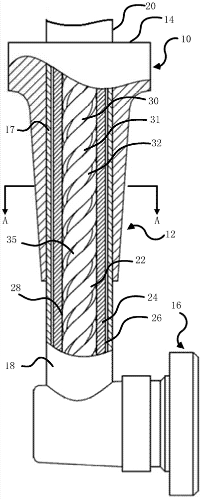
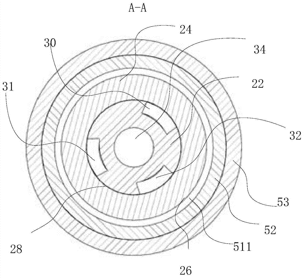
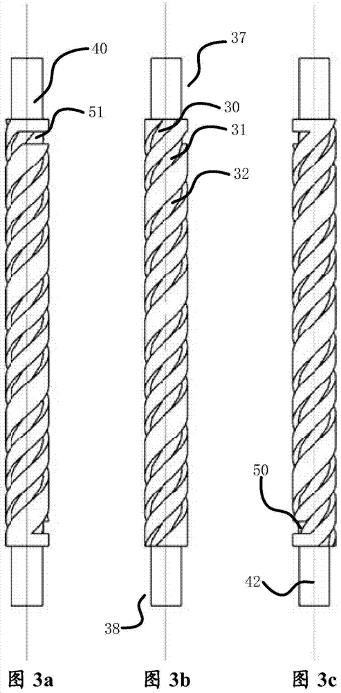
[0053] see figure 1 , figure 2 , Figure 3a , Figure 3b and Figure 3c , Embodiment 1 of the present invention provides a nozzle rod 12 , the nozzle rod 12 includes a rod-shaped body and a main oil passage 34 and an auxiliary oil passage 35 arranged on the rod-shaped body. Wherein: the auxiliary oil passage 35 is arranged around the main oil passage 34 , and the fluid in the main oil passage 34 and the fluid in the auxiliary oil passage 35 can exchange heat through the medium between the auxiliary oil passage 35 and the main oil passage 34 . The fluid that enters through the inlet of the main oil passage 34 can flow out through the outlet of the main oil passage 34; The position of the outlet port of the oil passage 34 turns back to the position close to the position of the inlet port of the main oil passage 34 , and then flows out through the oil outlet port of the auxiliary oil passage 35 .
[0054] see figure 2 , the heat insulation cavity 511 is filled with low th...
Embodiment 2
[0073] see Figure 4 , Figure 5 and Figure 6 The technical solutions of this embodiment and the above embodiments have the following differences: the number of hollow passages included in the auxiliary oil passage 135 is different, and the specific realization of the grooves forming the hollow passages is different. In this embodiment, the auxiliary oil passage 135 includes two hollow passages that are not connected to each other. The structures of the hollow passages may be the same or different, and the same is used as an example here. The grooves of each hollow passage include three linear grooves 130 , 131 , 132 , the linear grooves 130 and 131 are connected through a connecting section 150 , and the linear grooves 131 and 132 are connected through a connecting section 151 . The communication sections 150 and 151 may be circumferential, or have a certain angle with the axial direction, and the like. Preferably, both the communication sections 150, 151 are circumferent...
Embodiment 3
[0085] This embodiment has the following differences from the technical solutions of the above two embodiments. The hollow channel is formed in a different way. In this embodiment, the hollow channel is jointly formed by a groove provided on the inner wall of the fuel casing and the outer wall of the central pipeline, and the outer wall of the central pipeline is a smooth outer wall.
[0086] In this embodiment, the groove forming the hollow channel may also adopt the implementation methods in the above-mentioned embodiments, such as a spiral groove or a linear groove. Similarly, the number of spiral grooves and whether the spiral grooves are directly connected or connected through a transition part can refer to the content described above. The number of linear grooves and whether the linear grooves are directly connected or connected through transition parts can also refer to the content described above, and will not be repeated here.
[0087] Compared with the prior art, th...
PUM
 Abstract
Description
Claims
Application Information
 - R&D
- Intellectual Property
- Life Sciences
- Materials
- Tech Scout
- Unparalleled Data Quality
- Higher Quality Content
- 60% Fewer Hallucinations
Browse by: Latest US Patents, China's latest patents, Technical Efficacy Thesaurus, Application Domain, Technology Topic, Popular Technical Reports.
© 2025 PatSnap. All rights reserved.Legal|Privacy policy|Modern Slavery Act Transparency Statement|Sitemap|About US| Contact US: help@patsnap.com


