
Fuel oil burner for incinerator

A technology of burners and incinerators, which is applied in the direction of burners, lighting and heating equipment, etc. It can solve the problems of high ignition failure rate, expensive imported burners, and easy burnout of diffuser disc components, so as to save costs and ensure service life , Solve the effect that the oil nozzle is easy to coke

Pending Publication Date: 2020-02-07
上海迎韦热能设备有限公司
View PDF0 Cites 0 Cited by
  • Summary
  • Abstract
  • Description
  • Claims
  • Application Information

AI Technical Summary

Problems solved by technology

[0002] With the implementation of the new national standard for waste incineration emissions and the strong support of national policies, the oil burners of incinerators have developed rapidly, and the combustion technology has gradually improved and become more abundant. However, the current waste incinerator burners mainly use imported internationally renowned brands. Starting and auxiliary burners, imported burners are relatively expensive, and do not conform to the actual situation in China, and the ignition failure rate is high; moreover, when the temperature in the combustion chamber reaches 850-1100 °C, the starting burner stops working at this time, and the auxiliary combustion The burner continues to work to maintain the temperature in the furnace. During this period, the oil nozzle on the oil gun assembly of the start burner is easy to coke and block, and the diffuser assembly is covered by garbage and is easy to burn out; the maintenance cost is high

Method used


Image

  • Fuel oil burner for incinerator
  • Fuel oil burner for incinerator
  • Fuel oil burner for incinerator

Examples


Embodiment Construction

[0031] In order to have a further understanding and understanding of the structural features of the present invention and the achieved effects, the preferred embodiments and accompanying drawings are used for a detailed description, as follows:

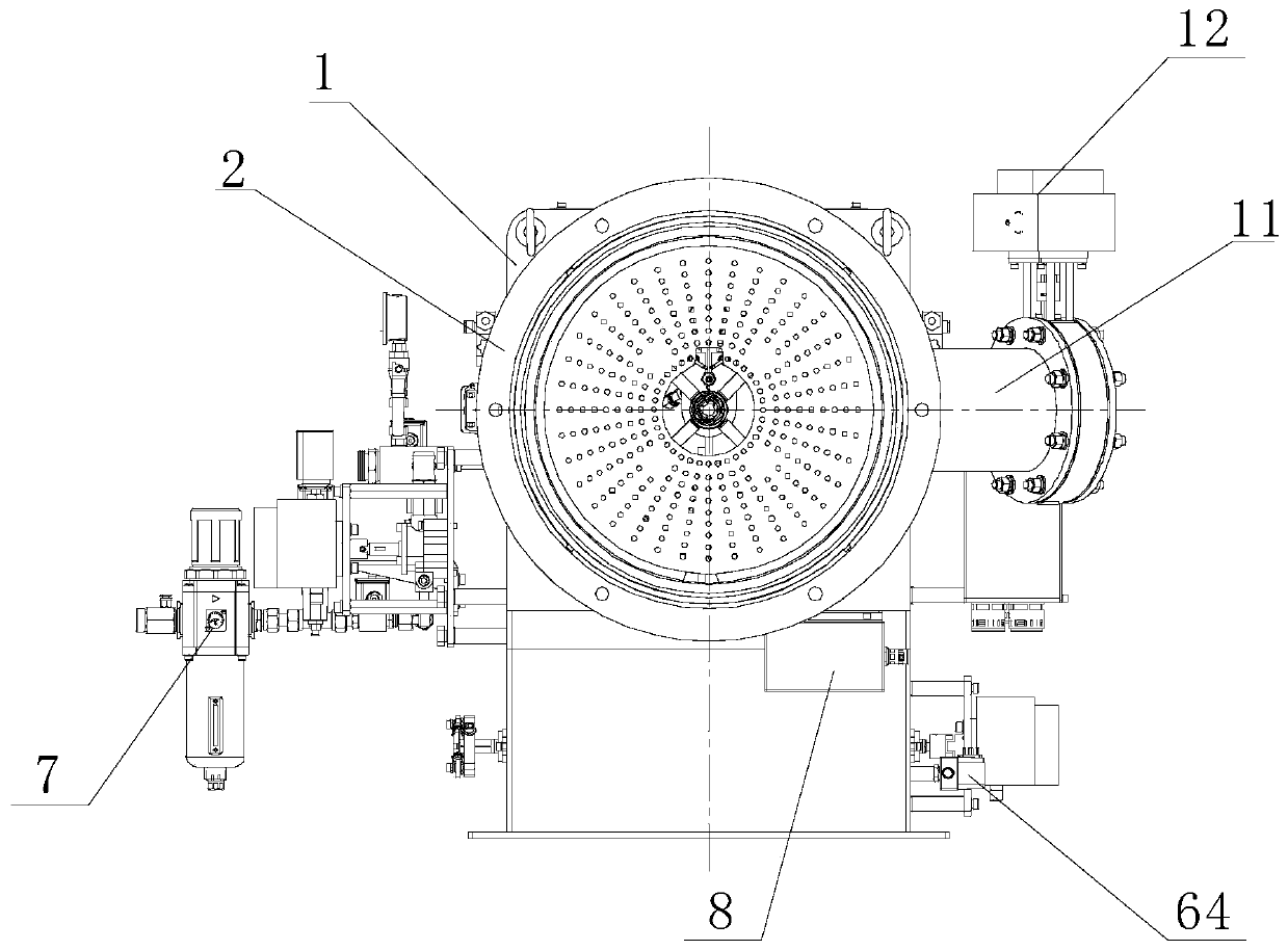
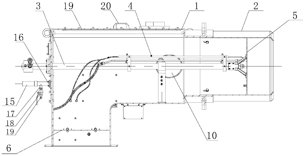
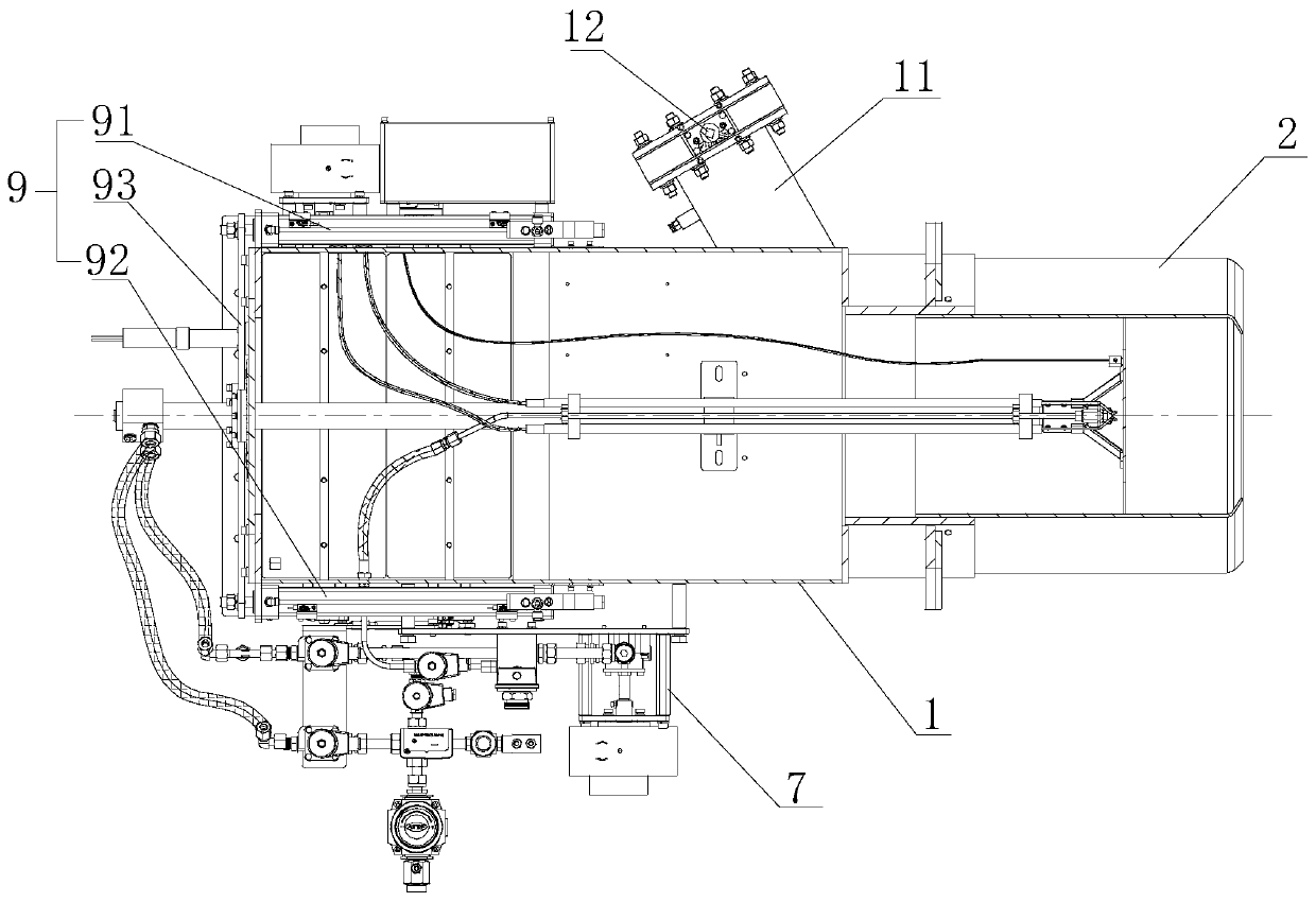
[0032] Such as Figure 1-5 As shown, an oil burner for an incinerator includes a burner housing 1, a flame tube 2, an oil gun assembly 3, an ignition needle assembly 4, a diffusion disc 5, a damper adjustment mechanism 6, an oil circuit module 7, The ignition transformer 8, the flame cylinder 2 are arranged at the front end of the burner housing 1, the diffuser plate 5 is arranged in the flame cylinder 2, the oil gun assembly 3 is arranged at the center of the inner chamber of the burner housing 1, and its front end extends to At the diffuser plate 5, the ignition needle assembly 4 is installed on the oil gun assembly 3, and its front end extends to the diffuser plate 5, the damper adjustment mechanism 6 is arranged at the bottom of t...


PUM


Abstract

The invention relates to a fuel oil burner for an incinerator. The fuel oil burner comprises a burner shell, a flame tube, an oil gun assembly, an ignition needle assembly, a diffusion disc, an air door adjusting mechanism, an oil circuit module and an ignition transformer, wherein an openable and closable cooling air inlet is arranged on one side of the front end of the burner shell; the diffusion disc is fixedly arranged at the front end of the oil gun assembly and forms a whole with the oil gun assembly; and the fuel oil burner further comprises an oil gun assembly advancing and retreatingdriving mechanism, and the oil gun assembly advancing and retreating driving mechanism is connected with the oil gun assembly and then drives the whole oil gun assembly to advance and retreat so as todrive the diffusion disc to move between the flame tube and the cooling air inlet. The fuel oil burner has the beneficial effects that the problems in the prior art that an oil nozzle on the oil gunassembly is prone to coking and the diffusion disc is prone to being burned out are effectively solved, and therefore the service life of the fuel oil burner is ensured and the cost for enterprises issaved.

Description

technical field [0001] The invention relates to the technical field of burners, in particular to an oil burner used in an incinerator. Background technique [0002] With the implementation of the new national standard for waste incineration emissions and the strong support of national policies, the oil burners of incinerators have developed rapidly, and the combustion technology has gradually improved and become more abundant. However, the current waste incinerator burners mainly use imported internationally renowned brands. Starting and auxiliary burners, imported burners are more expensive, and do not conform to the actual situation in China, and the ignition failure rate is high; moreover, when the temperature in the combustion chamber reaches 850-1100°C, the starting burner stops working at this time, and the auxiliary combustion The burner continues to work to maintain the temperature in the furnace. During this period, the oil nozzle on the oil gun assembly of the star...

Claims


Application Information

Patent Timeline
Patent Type & Authority Applications(China)
IPC IPC(8): F23D11/24F23D11/36
CPCF23D11/24F23D11/36
Inventor 李顺荣孙玉东林勇
Owner 上海迎韦热能设备有限公司
Learn More