Oil-gas composite cooling type flame stabilizer and combustion chamber

A technology of flame stabilizer and composite cooling, which is applied in combustion chambers, continuous combustion chambers, combustion methods, etc., can solve the problems of easy coking, clogging and ablation of fuel injection rods, and achieve enhanced flame stability, high-efficiency cooling, and increased The effect of dwell time

Active Publication Date: 2022-01-07
NANJING UNIV OF AERONAUTICS & ASTRONAUTICS
View PDF6 Cites 0 Cited by
  • Summary
  • Abstract
  • Description
  • Claims
  • Application Information

AI Technical Summary

Problems solved by technology

[0004] Purpose of the invention: The present invention provides an oil-gas composite cooling flame stabilizer, which solves the problems in the prior art that the blunt body flame stabilizer is easy to ablate in the high-temperature incoming flow and high-temperature flame in the wake area, and the fuel injection rod is easy to coke and block Problem, the oil-air composite cooling flame stabilizer can reduce the temperature of all the outer walls of the stabilizer, prevent fuel coking, improve the fuel evaporation effect, and improve the working reliability and stability of the flame stabilizer

Method used


Image

  • Oil-gas composite cooling type flame stabilizer and combustion chamber
  • Oil-gas composite cooling type flame stabilizer and combustion chamber
  • Oil-gas composite cooling type flame stabilizer and combustion chamber

Examples


Embodiment Construction

[0020] In order to make the object, technical solution and effect of the present invention more clear and definite, the technical solution of the present invention will be further described in conjunction with the accompanying drawings and embodiments. It should be understood that the specific implementations described here are only used to explain the present invention, not to limit the present invention.

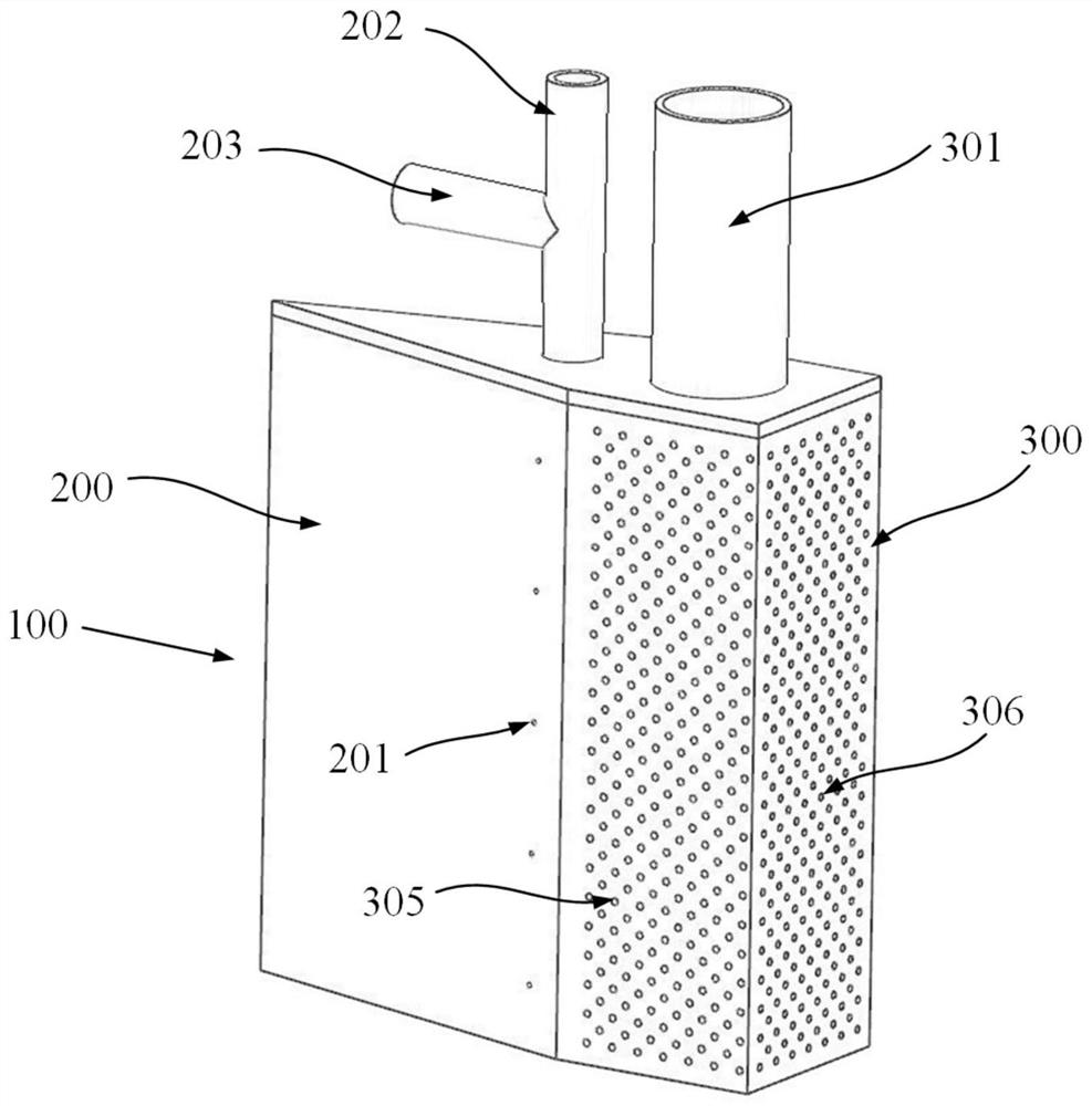
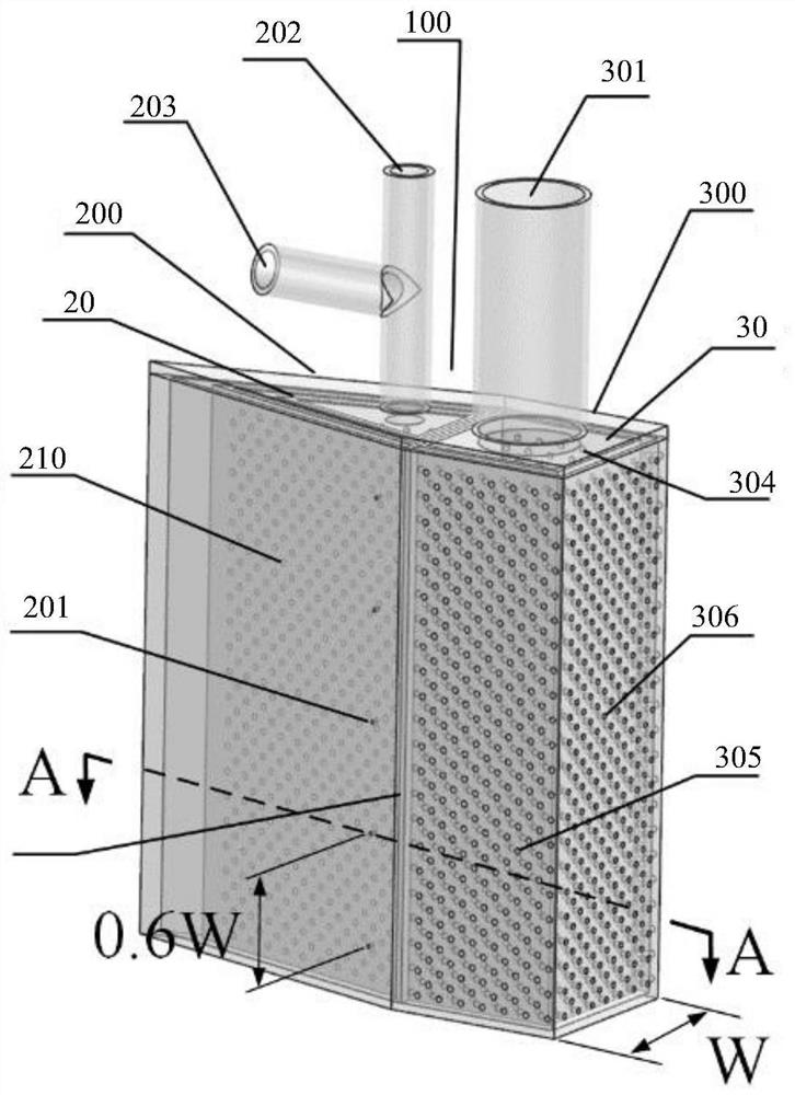
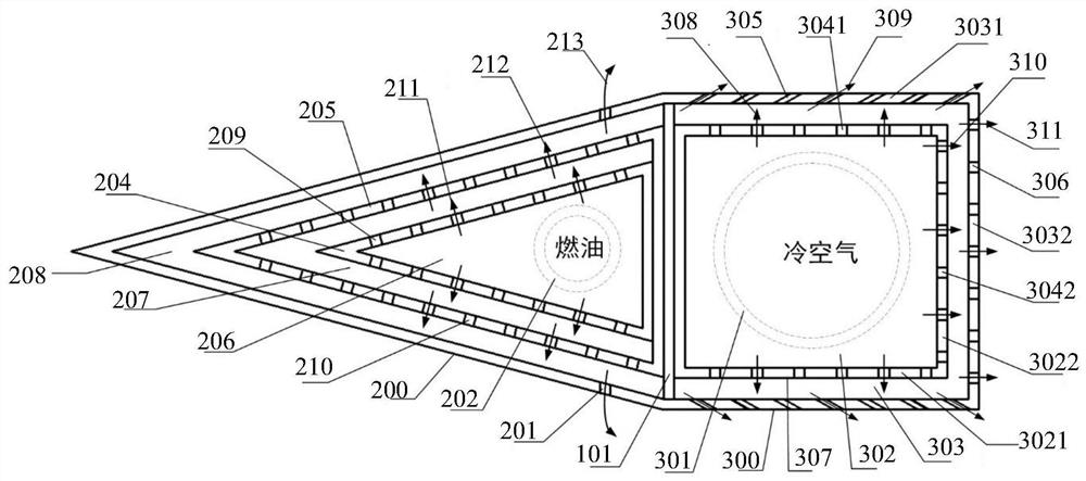
[0021] Such as figure 1 As shown, the oil-air composite cooling flame stabilizer of the present invention includes a flame stabilizer main body 100 , the hollow flame stabilizer main body 100 is divided into a V-shaped section 200 and a straight section 300 downstream of the V-shaped section 200 by a partition 101 . The V-shaped section 200 is a hollow cavity with a triangular cross-section. The internal cavity of the V-shaped section 200 is divided into several layers of interconnected oil cooling chambers 20 from the inside to the outside. Several fuel impact holes on t...


PUM


Abstract

The invention discloses an oil-gas composite cooling type flame stabilizer and a combustion chamber. The flame stabilizer comprises a flame stabilizer main body, wherein the flame stabilizer main body is divided into a V-shaped section and a straight section by a partition plate; an inner cavity of the V-shaped section is divided into a plurality of layers of oil cooling cavities which are in communication with one another from inside to outside; an inner cavity of the straight section is in communication with a cooling gas guide pipe, and a plurality of through holes used for sending out gas sent by the cooling gas guide pipe are formed in the outer wall of the straight section; and fuel oil passes through the oil cooling cavity and then is vertically injected into the high-temperature main flow through fuel oil injection holes. Cold air enters an air cooling cavity through the cooling gas guide pipe, then part of the cold air forms an air film on the side wall face through air film holes, the rest of the cold air enters the near-wall area of the rear end face of the stabilizer through cold air jet holes to form cold air vortexes, the wall temperature of the straight section of the stabilizer can be reduced, and the oxygen content and combustion efficiency in the wake area of the stabilizer can be improved.

Description

technical field [0001] The invention relates to the technical field of aerodynamic propulsion systems, in particular to an oil-gas composite cooling flame stabilizer and a combustion chamber. Background technique [0002] With the continuous development of advanced aerodynamic propulsion technology, in order to achieve a greater thrust-to-weight ratio, the temperature rise of the main combustion chamber of the turbofan and combined engine increases, and the temperature of the gas in front of the turbine increases significantly, so that the gas entering the afterburner / ram combustion chamber The flow temperature is greatly increased. The temperature of the incoming flow is getting higher and higher, the heat load of each component is increasing, and its fuel supply scheme is becoming more and more complex. The fuel can be used to cool part of the heat of the afterburner / ram combustion chamber before being injected into the high temperature incoming flow end parts. In additi...

Claims


Application Information

Patent Timeline
Patent Type & Authority Applications(China)
IPC IPC(8): F23R3/20F23R3/28
CPCF23R3/20F23R3/283
Inventor 范育新陈玉乾毕亚宁陶华黄学民
Owner NANJING UNIV OF AERONAUTICS & ASTRONAUTICS
Why Eureka
Try Eureka