
Underground pipeline testing method based on strain membranes

A technology of strained film and testing method, which is applied in the direction of electric/magnetic solid deformation measurement, electromagnetic measuring device, material resistance, etc., can solve the problems of inconvenient maintenance for management personnel, inability to locate immediately, reduction of induction speed and induction effect, etc., to achieve The effect of reducing pipeline maintenance costs

Inactive Publication Date: 2015-06-17
巫立斌
View PDF7 Cites 0 Cited by
  • Summary
  • Abstract
  • Description
  • Claims
  • Application Information

AI Technical Summary

Problems solved by technology

Underground pipelines include cables, heating pipes, water supply pipes, gas pipes, etc. Since they are buried underground, once a rupture occurs, they cannot be located immediately, which brings inconvenience to the maintenance of the management personnel.
What's more, it can cause more serious danger after being unable to locate immediately, resulting in the loss of personnel and property
Underground pipelines live in the dark and dark underground for a long time. Even if a leak occurs, it is mostly sensed based on the sensor measuring the amount of the leaking object. In consideration of cost, the sensors are set at a certain distance and cannot be spread throughout the pipeline. The sensing speed and sensing effect are greatly reduced, and some small cracks on the pipeline cannot be sensed even if they need to be sensed after a leak occurs, and often small cracks are easy to repair, and once a leak occurs, then It is very likely to cause heavy loss of property, or even casualty

Method used


Image

  • Underground pipeline testing method based on strain membranes
  • Underground pipeline testing method based on strain membranes
  • Underground pipeline testing method based on strain membranes

Examples


Embodiment 2

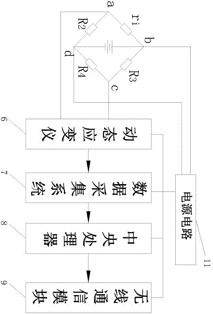
[0056] refer to Figure 4 As shown, this embodiment is basically the same as Embodiment 1, except that every n ring-shaped strained thin films 2 are connected in parallel through wires 10 to form a strained thin film group B. The equivalent circuit is also the same as that of the first embodiment. The equivalent resistance of the strained film group B is Ri, and this equivalent circuit is connected to the b terminal of the bridge circuit 5. When the pipeline 1 is broken or slightly deformed, the corresponding annular strained film 2 is slightly deformed or broken, so that The equivalent resistance ri of the strained film group changes, and the bridge circuit converts the resistance change of the strained film group ri (i=1~3) into a voltage change, and the voltage change is amplified and filtered by the dynamic strain gauge 6 to obtain The signal prototype, the signal prototype is sent to the data acquisition system for data storage, and sent to the central processing unit 8,...


PUM

PropertyMeasurementUnit
sizeaaaaaaaaaa

Abstract

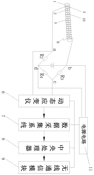
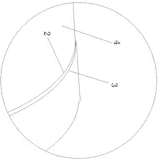
The invention relates to the technical field of underground pipeline survey and provides an underground pipeline testing method based on strain membranes. The method comprises the following steps: adhering N-numbered ring-shaped strain membranes to the surface of a pipeline uniformly, and adhering a waterproof membrane to the surface of each ring-shaped strain membrane, wherein N is not less than 2; arranging an insulating membrane isolator between two adjacent ring-shaped strain membranes; connecting every n-numbered ring-shaped strain membranes by conductors in series or in parallel to form strain membrane groups, wherein n is not less than 1 and not more than N; arranging n-numbered dynamic strain gauges, data acquisition systems, central processing units and wireless communication modules, which are connected with each other in sequence, to form operational circuits; connecting each strain membrane group with resistors R2, R3 and R4 end to end in sequence to form bridge circuits, wherein each bridge circuit is connected with each operational circuit; all the operational circuits communicate with a background database and a monitoring center via a wireless communication network. The method is accurate in positioning.

Description

technical field [0001] The invention relates to the technical field of underground pipeline measurement, in particular to a method for testing underground pipelines based on a strain film. Background technique [0002] With the development of urban construction, the scale and types of underground pipeline distribution are increasing dramatically. Underground pipelines include cables, heating pipelines, water supply pipelines, gas pipelines, etc., because they are buried underground, once they break, they cannot be located immediately, which brings inconvenience to the maintenance of management personnel. What's more, it can cause more serious danger after being unable to locate immediately, resulting in the loss of personnel and property. Underground pipelines live in the dark and dark underground for a long time. Even if a leak occurs, it is mostly sensed based on the sensor measuring the amount of the leaking object. In consideration of cost, the sensors are set at a cert...

Claims


Application Information

Patent Timeline
Patent Type & Authority Applications(China)
IPC IPC(8): G01N27/04G01B7/16
Inventor 巫立斌
Owner 巫立斌
Learn More