
LED dimming device based on PWM

A dimming device and LED driving technology, which is applied in the field of dimming circuits, can solve problems such as the inconsistency between the average current and the peak current, and achieve the effects of simple structure, good dimming effect, and stable LED driving circuit

Inactive Publication Date: 2015-06-17
吴汉肱
View PDF0 Cites 5 Cited by
  • Summary
  • Abstract
  • Description
  • Claims
  • Application Information

AI Technical Summary

Problems solved by technology

[0002] LED lamps are becoming more and more popular. The luminous efficiency of LED lamps has surpassed the level of ordinary fluorescent lamps. It has the advantages of high luminous efficiency, long life, energy saving and environmental protection. However, the research on LEDs is changing with each passing day. It is generally believed that constant current drive LED lamps are The best choice, the current control method has the mainstream peak current control, but it has the problem that the average current is inconsistent with the peak current

Method used


Image

  • LED dimming device based on PWM

Examples


Embodiment Construction

[0009]

[0010] In order to make the object, technical solution and advantages of the present invention clearer, the present invention will be further described in detail below in conjunction with the accompanying drawings.

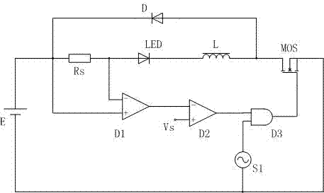
[0011] refer to figure 1 The structural representation of the present invention shown.

[0012] The LED dimming device of the embodiment of the present invention includes an LED drive unit, a current detection unit, and a hysteresis control unit. The LED drive unit is composed of an inductor L and a freewheeling diode D, and controls the on-off of the LED through a MOS tube. The current detection The unit includes a sampling resistor Rs connected in series to the LED lamp and a differential amplifier D1 connected in parallel to the sampling resistor Rs. The hysteresis control unit is composed of an amplifier D2 and a NAND gate D3. The negative input terminal of the amplifier D2 is connected to the differential amplifier. The output terminal of the ampli...


PUM


Abstract

The embodiment of the invention discloses an LED dimming device based on PWM. The device comprises an LED driving unit, a current detecting unit and a hysteresis control unit, wherein the LED driving unit is composed of an inductor L and a fly-wheel diode, and LEDs are controlled to be turned on or off through an MOS transistor. The current detecting unit comprises a sampling resistor connected to an LED lamp in series and a differential amplifier connected to the sampling resistor in parallel; the hysteresis control unit is composed of an amplifier and a not-and gate; the negative input end of the amplifier is connected with the output end of the differential amplifier, a set threshold voltage is input to the positive input end of the amplifier, the output end of the not-and gate is connected with a gate pole of the MOS transistor, and the input of the not-and gate is connected with the output end of the amplifier and a digital dimming signal. Due to the adoption of the LED dimming device, a current hysteresis control mode is used for solving the problem that peak current and average current are not consistent during current peak control, the subharmonic oscillation phenomenon with the duty ratio larger than 0.5 occurring during peak current control is avoided, and therefore a slope compensation circuit is not needed, and the circuit structure is relatively simple.

Description

technical field [0001] The invention relates to a dimming circuit, in particular to a PWM-based LED dimming device. Background technique [0002] LED lamps are becoming more and more popular. The luminous efficiency of LED lamps has surpassed the level of ordinary fluorescent lamps. It has the advantages of high luminous efficiency, long life, energy saving and environmental protection. However, the research on LEDs is changing rapidly. It is generally believed that constant current drive LED lamps are The best choice, the current control method has the mainstream peak current control, but it has the problem that the average current is inconsistent with the peak current. Contents of the invention [0003] The technical problem to be solved by the embodiments of the present invention is to provide a PWM-based LED dimming device. It can stably solve the shortcomings of peak current control. [0004] In order to solve the above technical problems, an embodiment of the pres...

Claims


Application Information

Patent Timeline
Patent Type & Authority Applications(China)
IPC IPC(8): H05B37/02
CPCY02B20/40
Inventor 吴汉肱
Owner 吴汉肱
Learn More