
Method for modifying the flanks of a tooth of a gear wheel with the aid of a tool

A technology for dressing wheels and gear teeth, applied in the direction of gear tooth manufacturing devices, manufacturing tools, components with teeth, etc.

Active Publication Date: 2015-06-17
PRAWEMA ANTRIEBSTECHN
View PDF11 Cites 2 Cited by
  • Summary
  • Abstract
  • Description
  • Claims
  • Application Information

AI Technical Summary

Problems solved by technology

The shape of the narrow dressing wheel does not need to coincide with the workpiece toothing in all parameters, nor does it require complex additional maneuvering possibilities in the corresponding dressing device

Method used


Image

  • Method for modifying the flanks of a tooth of a gear wheel with the aid of a tool
  • Method for modifying the flanks of a tooth of a gear wheel with the aid of a tool
  • Method for modifying the flanks of a tooth of a gear wheel with the aid of a tool

Examples


Embodiment Construction

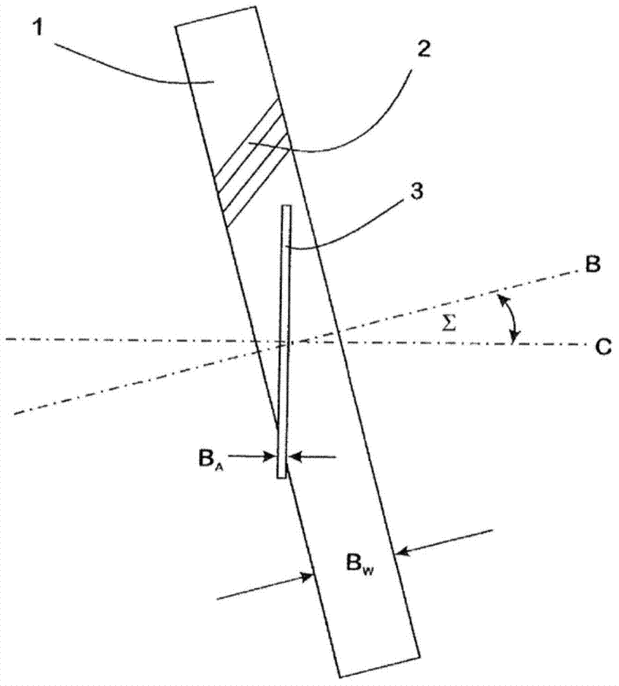
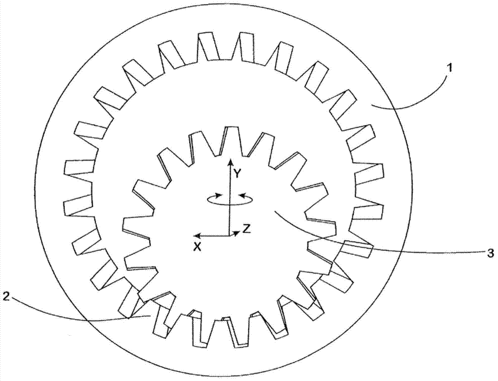
[0032] exist figure 1 The tool 1 shown in is used for honing the toothing of a gear Z with external helical toothing. For this purpose, the tool is of annular construction and has internally beveled toothing 2 .

[0033] A dressing wheel 3 is provided for dressing the tool 1 .

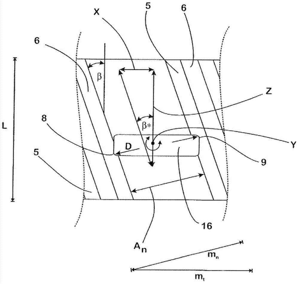
[0034] Width B of dressing wheel 3 A Usually less than the width B of the tool 1 to be trimmed W one-eighth of. so that the dressing wheel 3 in order to run over the width B of the tool 1 W Then it must be correspondingly larger than the width B of the dressing wheel 3 A Eight times the length L, while moving in the direction of its rotation axis C (moving axis Z or Z direction).

[0035] In the figures, neither the spatial arrangement nor the width ratio are shown in a proportionally correct manner.

[0036] In order to adjust the dressing wheel relative to the tool 1 to be dressed in the Z direction and perpendicular thereto in the X direction (movement axis X), an individually controllable ad...


PUM


Abstract

The invention relates to a method for modifying the geometry of gear wheel tooth flanks using a tool having a toothing that engages with the gear wheel (ZR) during precision machining. In this case, a profile that varies over the width (Bw) of the tool (1) is produced on the tool (1) in that, during a dressing operation, a dressing wheel (3) is moved along the tooth flank (5) of the tooth (6) to be dressed. The width of the teeth (16) of the dressing wheel (3) is much smaller than the width (Bw) of the tool (1). Therefore, in order to pass over the width (Bw) of the tool (1), it must be moved by a length (L) corresponding to a multiple of the width (BA) of the teeth (16) of the dressing wheel (3). After dressing, the precision machining of the gear wheel (ZR) using the tool (1) takes place. Since, in the process, the dressing wheel (3) is moved with a changing pitch and a changing crossed axes angle (Σ) with respect to the tool (1), the modification of the tooth flank geometry can be transferred to the tool (1). During the subsequent precision machining, a modification of the crossed axes angle (Σ) takes place during the machining process, said modification being dependent on the helix angle of the tool (1), with the helix angle of the tool (1) being compensated, said helix angle changing over the width of the teeth (16) of the tool.

Description

technical field [0001] The invention relates to a method for finishing the geometry of the tooth flanks of a gear by means of a tool having meshing teeth which engage with the teeth of the gear during finishing. Background technique [0002] The content of DE 10 2007 043 402 A1 is included in the disclosure content of the present application, which discloses that, during the finishing process, by adding the necessary forming parts for various geometric deformations in the tool used for finishing, Dressing on the contour of the gear to be finished is thus carried out in a very economical and at the same time very efficient manner from a technical point of view. In this regard, this known method is characterized in that a narrow dressing wheel is used for dressing, the width of which is ideally smaller than the width of the corresponding tooth to be machined, so that the dressing wheel is only A contact line or a contact area reduced to a point runs over the tooth flank to be...

Claims


Application Information

Patent Timeline
Patent Type & Authority Applications(China)
IPC IPC(8): B23F23/12B23F19/00B23F19/05
CPCB23F19/002B23F19/057B23F23/1231
Inventor 约尔格·席克
Owner PRAWEMA ANTRIEBSTECHN
Learn More