

Image pick-up element and image pick-up device
A technology of imaging elements and pixels, which is applied in focusing devices, optical elements, electrical elements, etc., can solve the problem of not being able to perform focus detection and image information generation at the same time.
- Summary
- Abstract
- Description
- Claims
- Application Information
AI Technical Summary
Problems solved by technology
Method used
Image

Examples
no. 1 Embodiment approach
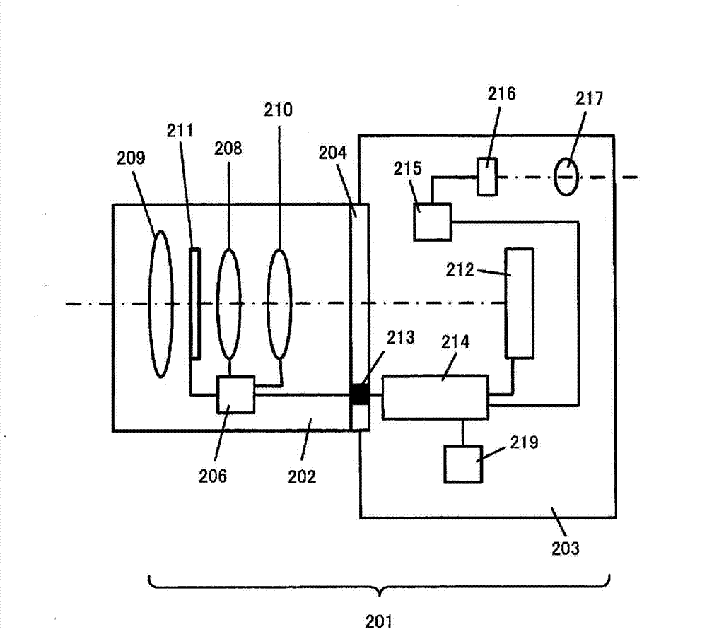
[0069] An imaging element and an imaging device according to a first embodiment of the present invention will be described. figure 1 It is a cross-sectional view showing the structure of an interchangeable-lens digital still camera equipped with the imaging element of the first embodiment. A digital still camera 201 according to the first embodiment includes an interchangeable lens 202 and a camera body 203 , and various interchangeable lenses 202 are mounted on the camera body 203 via a mount 204 .
[0070] The interchangeable lens 202 has a lens 209 , a zoom lens 208 , a focus lens 210 , a diaphragm 211 , a lens drive control device 206 , and the like. The lens drive control device 206 is composed of a microcomputer, a memory, a drive control circuit, and the like (not shown). The lens driving control device 206 performs drive control for adjusting the focus of the focusing lens 210 and adjusting the opening diameter of the aperture 211, and detection of the states of the z...
no. 2 Embodiment approach
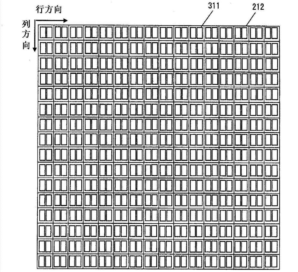
[0148] In the first embodiment, the pair of photoelectric conversion units 13 and 14 of the focus detection pixel 311 are arranged side by side in the horizontal direction (row direction). However, by setting the direction in which the pair of photoelectric conversion sections of the focus detection pixel are arranged side by side to be other than the horizontal direction (row direction), image shift detection can be performed in directions other than the horizontal direction. Figure 17 is to show the Figure 6 A diagram of a focus detection pixel 312 of a configuration in which the focus detection pixel 311 is shown rotated by 90 degrees. The focus detection pixel 312 is composed of a rectangular microlens 10 and a pair of photoelectric conversion parts 16 and 17 divided into two by an element isolation region 18 extending in the horizontal direction. When the pair of photoelectric conversion sections 16 and 17 are combined, they have the same size as a photoelectric conver...
no. 3 Embodiment approach
[0157] In the first embodiment, all pixels are constituted by focus detection pixels. However, it is possible to reduce the number of focus detection pixels in the entire imaging element and simplify the configuration of the imaging element by mixing normal imaging pixels without a divided photoelectric conversion section and focus detection pixels with a divided photoelectric conversion section. In addition, by reducing the number of focus detection data output from the imaging element to the outside, the data transfer rate of the focus detection data can be made equal to the data transfer rate of the image processing data.
[0158] Such as Figure 22 As shown, the imaging pixel 310 has a rectangular microlens 10 and a photoelectric conversion unit 11 whose light-receiving area is limited by a light shield described later.
[0159] Figure 23 yes Figure 22 A cross-sectional view of the camera pixel 310 is shown. In the imaging pixel 310 , a light shield 30 is formed clos...
PUM
 Abstract
Description
Claims
Application Information