

Semiconductor memory
a technology of semiconductor devices and memory cells, applied in semiconductor devices, digital storage, instruments, etc., can solve the problems of limitation of conventional memory cells in implementing high-speed performance of cells, and achieve the effect of preventing the occurrence of read disturbances
- Summary
- Abstract
- Description
- Claims
- Application Information
AI Technical Summary
Benefits of technology
Problems solved by technology
Method used
Image

Examples
first preferred embodiment
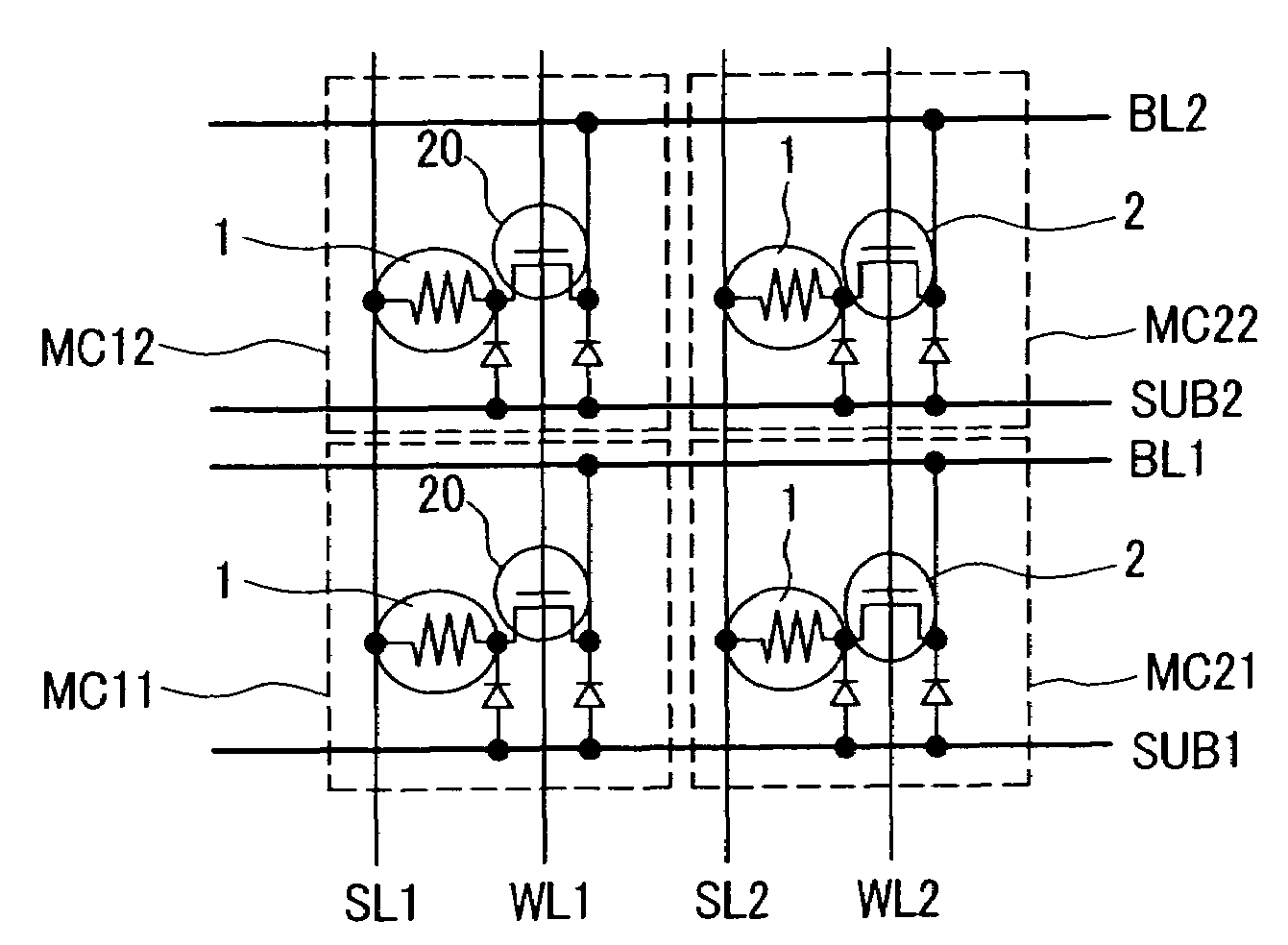
[0051]FIG. 1 is a structural diagram illustrating a memory array according to the present invention. A method for fabricating a memory array of FIG. 1 will hereinafter be described according to a fabrication process of the memory array. FIG. 1 shows only the memory array. An isolation layer 6 is formed as shown in FIG. 5. FIG. 5 is a top view illustrating a fabrication process of a semiconductor memory according to a first preferred embodiment of the present invention. In order to form the isolation layer 6, a trench groove is formed in a silicon substrate by general photolithography and dry-etching processes. A CMOS well is formed by a general fabrication method. An N-type well is formed in a memory array. In order to implement the memory array of FIG. 1, a substrate potential of the cell array is separated in the direction parallel to a bit line. For this purpose, only the memory array is exposed by the general photolithography, and a p-type diffusion layer 8 is deposited under th...
second preferred embodiment
[0072]The second preferred embodiment of the present invention relates to a method for implementing a phase-change memory array having superior noise resistance. For this purpose, the second preferred embodiment of the present invention employs a folded bit-line arrangement (i.e., a memory array including two intersection points) widely used for DRAMs. A fabrication process of the second preferred embodiment is almost similar to that of the first preferred embodiment. Also, the second preferred embodiment also uses a method for isolating each component using a gate electrode in the same manner as in the first preferred embodiment. The fabrication method of the second preferred embodiment will hereinafter be described with reference to the annexed drawings. A method for isolating each component, a method for forming a word-line electrode, and a method for forming an impurity diffusion layer of the second preferred embodiment are equal to those of the first preferred embodiment, and a...
third preferred embodiment
[0075]The first and second preferred embodiments have isolated each component by a combination of a shallow trench isolation and a field plate isolation. The third preferred embodiment employs only the shallow trench isolation. The third preferred embodiment does not use a gate electric field for isolation of each component, such that it can easily control a word system, and a detailed description thereof will hereinafter be described. N-type well is formed in the memory cell array using a P-type substrate. An isolation layer shown in FIG. 26 is formed by a typical CMOS process. Next, in order to isolate a substrate potential in a direction parallel to a bit line, a resist pattern of FIG. 27 is used as a mask, and implantation of P-type impurity is executed. FIG. 28 is a cross-sectional view illustrating a semiconductor memory taken along the line A-A of FIG. 27. A diffusion layer must be thicker than the isolation layer 6, differently from the example of FIG. 6. The remaining parts...
PUM
 Abstract
Description
Claims
Application Information