
Solid-liquid separation device for centrifugal machine

A solid-liquid separation and centrifuge technology, which is applied in the direction of filtration separation, separation methods, chemical instruments and methods, etc., can solve the problems of reducing the purity of solids, working hard for staff, and reducing production efficiency, so as to improve convenience and improve work efficiency. Efficiency and the effect of reducing the occupied space

Inactive Publication Date: 2015-06-24
张逸
View PDF3 Cites 1 Cited by
  • Summary
  • Abstract
  • Description
  • Claims
  • Application Information

AI Technical Summary

Problems solved by technology

However, in the actual application process, the liquid outlet pipe is often blocked due to the crystallization of the crystallized material. At this time, it is necessary to stop the machine immediately to clean the liquid outlet pipe, which reduces the production efficiency.
However, how to thoroughly clean the outlet pipe of the integrated structure also makes the staff work hard
[0003] Furthermore, some mother liquors to be treated often contain large volumes of colloids, particles, and sundries. When the centrifuge is working, some lighter impurities are easily thrown out, resulting in blockage of the outlet pipe, while some heavier Heavy impurities are mixed in the solids that need to be collected, such as copper powder, industrial grade monoammonium phosphate, etc., reducing the purity of solids

Method used


Image

  • Solid-liquid separation device for centrifugal machine
  • Solid-liquid separation device for centrifugal machine
  • Solid-liquid separation device for centrifugal machine

Examples


Embodiment

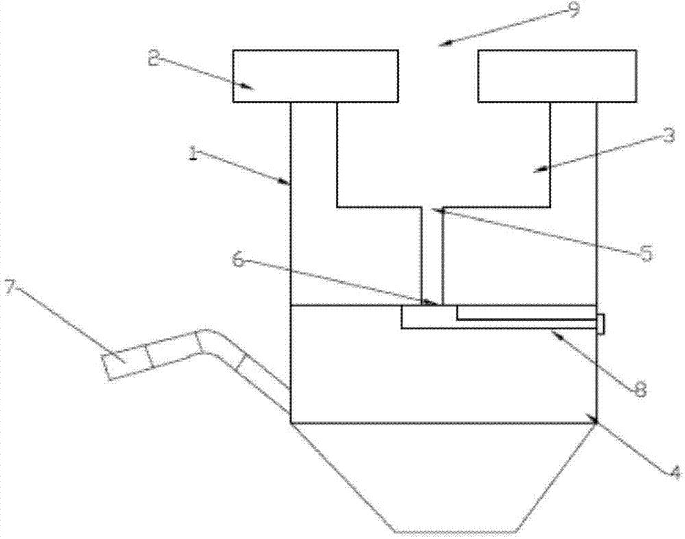
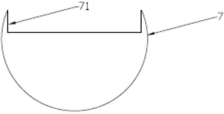
[0027] Such as figure 1 , figure 2 , image 3 As shown, this embodiment provides a solid-liquid separation device for a centrifuge, including a housing 1, a cover plate 2 buckled above the housing 1, a filter disc 3 located inside the housing 1 and connected to the bottom of the cover plate 2 And the centrifuge body 4 located at the lower end of the housing 1, the drain port 5 provided at the bottom of the filter plate 3 is connected to the liquid inlet 6 provided at the top of the centrifuge body 4 through a pipeline, and the centrifuge body 4 is also connected to a drain pipe 7. The inner wall of the drain pipe 7 is provided with a diversion groove 71 .

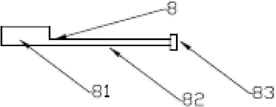
[0028] The centrifuge solid-liquid separation device also includes a movable plug 8 , and a part of the movable plug 8 is located inside the centrifuge body 4 . The movable plug 8 is composed of a plug head 81 inside the centrifuge body 4 , a fixed block 83 outside the centrifuge body 4 and a plug handle 82 connecting t...


PUM


Abstract

The invention provides a solid-liquid separation device for a centrifugal machine. The solid-liquid separation device comprises a shell, cover plates, a filter disc and a centrifugal machine body, wherein the cover plates are buckled at the upper part of the shell, the filter disc is located in the shell and is connected with the bottoms of the cover plates, and the centrifugal machine body is located at the lower end of the shell; a liquid outlet formed in the bottom of the filter disc and a liquid inlet formed in the top of the centrifugal machine body are connected through a pipeline; the centrifugal machine body is further connected with a liquid outlet pipe, and a flow guide groove is formed in the inner wall of the liquid outlet pipe. According to the solid-liquid separation device for the centrifugal machine, by forming the flow guide groove in the inner wall of the liquid outlet pipe, a phenomenon that a liquid draining passage is blocked by separated crystals of crystallized materials is avoided; large-particle impurities such as colloids are filtered by virtue of the filter disc before a mother solution is subjected to solid-liquid separation, so that the purity of separated solids is improved.

Description

technical field [0001] The invention relates to a centrifuge solid-liquid separation device. Background technique [0002] At present, the types and structures of solid-liquid separation devices are diversified, and these solid-liquid separation devices are used in different technical fields according to different product and process requirements. Existing solid-liquid separation devices mostly use a liquid outlet pipe with an integrated structure to output liquid. However, in the actual application process, the liquid outlet pipe is often blocked due to the crystallization of the crystallized material. At this time, it is necessary to stop the machine immediately to clean the liquid outlet pipe, which reduces the production efficiency. However, how to thoroughly clean the outlet pipe of the integrated structure also makes the staff work hard. [0003] Furthermore, some mother liquors to be treated often contain large volumes of colloids, particles, and sundries. When the ...

Claims


Application Information

Patent Timeline
Patent Type & Authority Applications(China)
IPC IPC(8): B01D36/04
Inventor 张逸
Owner 张逸
Learn More