Non-tangent expansion round steel hole type and production method

A tangent and round steel technology, applied in metal processing equipment, metal rolling, metal rolling, etc., can solve the problems of not meeting the high-precision requirements and difficult to meet the needs of high-precision bar rolling, and achieve easy processing and assembly Ease of operation, high degree of automation, and simplified mechanical equipment

Active Publication Date: 2015-06-24
GANSU JIU STEEL GRP HONGXING IRON & STEEL CO LTD
View PDF5 Cites 1 Cited by
  • Summary
  • Abstract
  • Description
  • Claims
  • Application Information

AI Technical Summary

Problems solved by technology

[0003] However, the finished pass designed by the above-mentioned traditional method, regardless of whether the width expansion part is circular expansion or tangential expansion, due to the large expansion angle design with a large degree of adjustment freedom, itself does not meet the high-precision requirements; on the other hand, the current domestic Bar rolling mill equipment itself is difficult to meet the needs of high-precision bar rolling

Method used


Image

  • Non-tangent expansion round steel hole type and production method
  • Non-tangent expansion round steel hole type and production method
  • Non-tangent expansion round steel hole type and production method

Examples


Embodiment 1

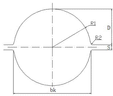
[0024] A non-tangential expansion round steel pass, which is composed of a base circle and non-tangential expansion parts located on both sides of the base circle. The specific dimensions of the base circle radius and notch width are as follows:

[0025] Base circle radius R1 =0.5×d×(1.007~1.02);

[0026] Notch width bk=d×(1.007~1.02)+(0.2~0.3);

[0027] Where: d is the nominal diameter of the round steel;

[0028] 1.007~1.02 is the coefficient of thermal expansion;

[0029] 0.2~0.3 is the groove width constant;

[0030] S is the roll gap, where S=1.5mm

[0031] D is the height of the groove bottom, D=R1-S / 2

[0032] R2 is the notch fillet radius, where R2=0.5mm.

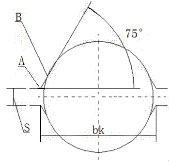
[0033] Said by figure 2 As shown, first determine the roll seam line on the base circle, the distance between the upper and lower two roll seam lines is S, determine A point on the roll seam line according to the notch width bk, and the horizontal distance between A point and the center of the base circle is S...

Embodiment 2

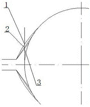
[0038] Depend on figure 2 , image 3 As shown, adopt this method to draw out the non-tangential expansion hole pattern, with embodiment 1, figure 2 It is a schematic diagram of the drawing process of the non-tangential expansion high-precision round steel pass; the traditional pass design method is used to draw the arc expansion pass and the tangential expansion pass, and this method is used to draw the non-tangential expansion pass; image 3 It is a schematic diagram of the diagonal size difference corresponding to the design methods of arc expansion pass, tangential expansion pass, and non-tangential expansion pass. In the figure, it can be known that the distance from the largest part 1 of the circular arc expansion to the base circle is the largest, and the tangent The distance from the part 2 with the largest expansion size to the base circle is second, and the distance from the part 3 with the largest non-tangential expansion size to the base circle is the smallest.


PUM


Abstract

The invention discloses a non-tangent expansion round steel hole type and a production method, and relates to the field of a steel rolling technology. The non-tangent expansion round steel hole type is composed of a base circle and width expansion parts located on the two sides of the base circle. By means of a non-tangent expansion hole type technology, the size of a diagonal line of the hole type is minimum, and accordingly ovality is minimum. Rolled grooves are easy and convenient to machine and assemble, the ovality of produced high-precision round steel is not larger than 0.20 mm, and the requirement for ovality of high-precision bars is met. Meanwhile, the service life of the grooves is prolonged, mechanical equipment is simplified through the round steel hole type, the produced round steel is good in stability and high in automation degree, and production efficiency and product quality are greatly improved.

Description

technical field [0001] The invention relates to a round steel pass, which belongs to the field of steel rolling technology, in particular to a non-tangential expansion round steel pass; the invention also relates to a production method of the non-tangential expansion round steel pass. Background technique [0002] There are usually two methods for the pass design of traditional hot-rolled round steel products: the first is that the width expansion part adopts circular arc expansion, that is, the double-radius arc method; the second is that the width expansion part adopts tangential expansion. [0003] However, the finished pass designed by the above-mentioned traditional method, regardless of whether the width expansion part is circular expansion or tangential expansion, due to the large expansion angle design with a large degree of adjustment freedom, itself does not meet the high-precision requirements; on the other hand, the current domestic Bar mill equipment itself is d...

Claims


Application Information

Patent Timeline
Patent Type & Authority Applications(China)
IPC IPC(8): B21B1/16
CPCB21B1/16B21B27/024
Inventor 寇劲松李定义杨超
Owner GANSU JIU STEEL GRP HONGXING IRON & STEEL CO LTD
Why Eureka
Try Eureka