
Plate stamping feeding device

The technology of a feeding device and plate parts is applied in the stamping field of metal plate parts, which can solve the problem of high cost and achieve the effects of compact structure, saving processing cost and energy, and saving power source.

Inactive Publication Date: 2015-06-24
ZHEJIANG SCI-TECH UNIV
View PDF5 Cites 5 Cited by
  • Summary
  • Abstract
  • Description
  • Claims
  • Application Information

AI Technical Summary

Problems solved by technology

[0003] The present invention provides a plate punching and feeding device, aiming to solve the problem of high cost caused by the need for an additional power source in the machine for supplementing plates in the prior art

Method used


Image

  • Plate stamping feeding device
  • Plate stamping feeding device
  • Plate stamping feeding device

Examples


Embodiment 1

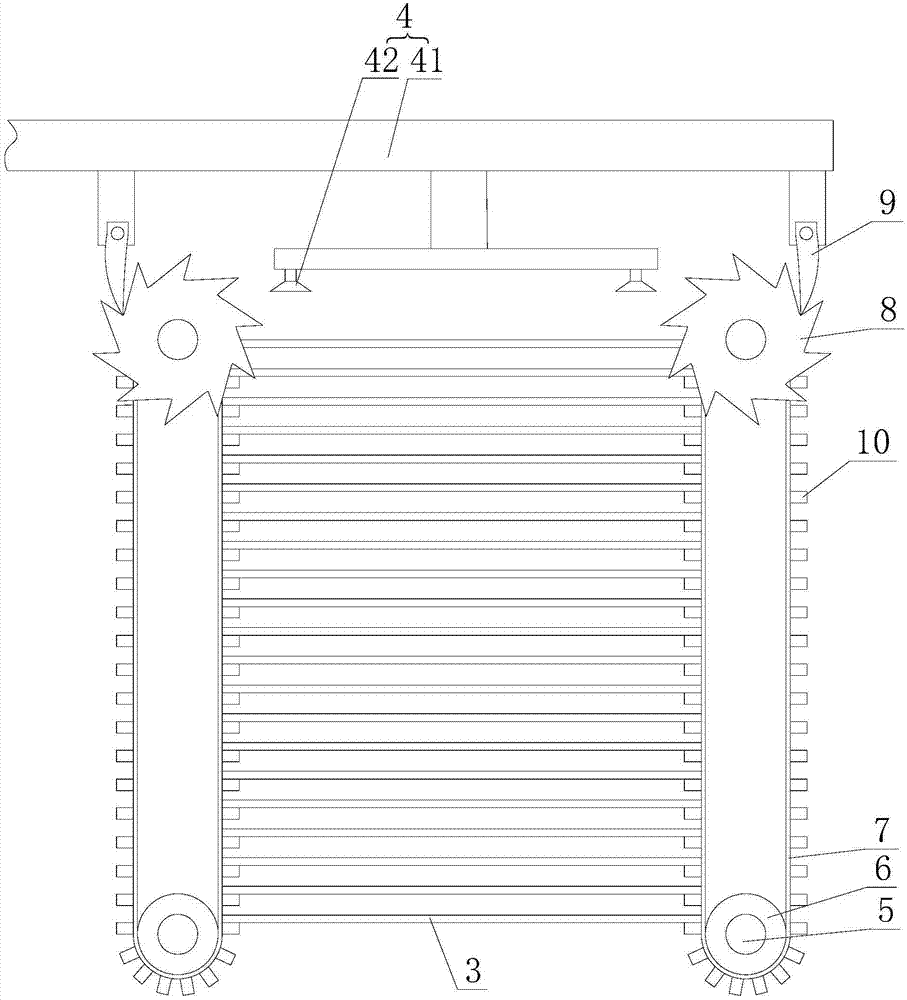
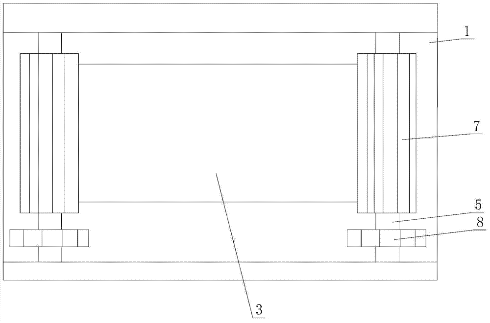
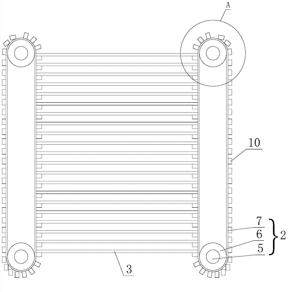
[0015] refer to figure 1 , figure 2 with image 3 , a plate stamping feeding device, including a support base 1, two sets of synchronous belt devices 2 symmetrically arranged on the support base 1, a manipulator 4 for taking a rectangular plate 3; each set of synchronous belt devices 2 It includes two upper and lower rotating shafts 5 arranged in the front and rear directions of the axis and transferred to the support base 1, two synchronous pulleys 6 respectively fixedly connected to the two rotating shafts 5, and a synchronous belt 7 arranged on the two synchronous pulleys 5. , evenly distributed on the outer surface of the synchronous belt 7 and used to support the support block 10 on one side of the plate 3; the rotating shaft 5 above the synchronous belt device 2 of each group is fixedly connected with a ratchet 8, and the manipulator 4 is connected with two left and right Drive the ratchets 9 of the two ratchets 8 respectively, the ratchet 9 on the left side is positi...

Embodiment 2

[0020] refer to Figure 4 , the difference from Embodiment 1 is that: the support block 10 is a plate with a rectangular cross section; each group of support blocks 10 is connected to the corresponding synchronous belt 7; when the support block on the left synchronous belt 7 When 10 is located on the right side of the left synchronous belt 7, the upper left corner of the support plate 10 is transferred to the left synchronous belt 7; when the support block 10 on the right synchronous belt 7 is located on the left side of the right synchronous belt 7, the Board 10 upper right corners are transferred on the synchronous belt 7 on the right side.

[0021] When the plate 3 rises, the plate 3 can easily push the support blocks 10 above it away, so that the distance between the support blocks 10 can be smaller, and more plate 3 can be placed.

[0022] In the present invention, two sets of synchronous belt devices are adopted, and two sets of support blocks respectively arranged on t...


PUM


Abstract

The invention provides a plate stamping feeding device. The plate stamping feeding device aims at solving the problem that the cost is high due to that additional power sources are needed in a plate supplementing machine in the prior art. The plate stamping feeding device comprises a supporting seat, two groups of synchronous belt devices and a mechanical arm; each group of synchronous belt device comprises two rotating shafts, two synchronous pulleys, a synchronous belt and a group of supporting blocks; rotating shafts arranged above each group of synchronous belt devices are fixedly connected with ratchet wheels, and the mechanical arm is rotatably connected with two paws which are in the left side and the right side. The plate stamping feeding device is composed of two groups of synchronous belt devices and two groups of supporting blocks which are arranged on the two groups of synchronous belt devices respectively and are used for supporting the plate, and the rise of a supporting plate is convenient; the ratchet wheels on the two groups of synchronous belt devices are controlled by the two paws on the mechanical arm respectively, so that the two groups of synchronous belt devices are driven to rotate, the plate is raised to cover a position, the mechanical arm is used for driving, additional power sources used for driving the two groups of synchronous belt devices are saved, and processing cost and energy resources are saved.

Description

technical field [0001] The invention relates to the field of stamping of metal plates, in particular to a plate stamping and feeding device. Background technique [0002] During the stamping process of the plate, the reciprocating motion path of the manipulator is the same. After the manipulator grabs a plate, the next plate needs to be supplemented to the position of the previous plate; at present, some factories use manual feeding, which is not only inefficient , and there are great potential safety hazards; some factories use machines to realize this process, but these require additional power sources, which are costly, waste electric energy, and have complex structures. Contents of the invention [0003] The present invention provides a board punching and feeding device, aiming to solve the problem in the prior art that the machine for replenishing boards needs an extra power source, thus resulting in high cost. [0004] In order to solve the above technical problems,...

Claims


Application Information

Patent Timeline
Patent Type & Authority Applications(China)
IPC IPC(8): B21D43/18B65G47/91
CPCB21D43/18B21D43/24
Inventor 高金标何利力
Owner ZHEJIANG SCI-TECH UNIV
Learn More