
Milling machine fixture capable of adjusting angle

A milling machine fixture and adjustable technology, applied in the mechanical field, can solve the problems of time-consuming and laborious clamping process, difficult to improve production efficiency, difficult to guarantee the angle, etc., and achieve the effect of improving processing efficiency and simple structure

Inactive Publication Date: 2015-06-24
UNIV OF JINAN
View PDF13 Cites 15 Cited by
  • Summary
  • Abstract
  • Description
  • Claims
  • Application Information

AI Technical Summary

Problems solved by technology

[0003] In modern machining, when milling a plane with an angle, the required angle is usually measured with a ruler, and then fixed by using pads, bolts, and pressure plates. The clamping process is time-consuming and laborious, and the angle is difficult to guarantee. When the angle changes, it needs to be repeated. It is difficult to improve production efficiency by performing the above operations

Method used


Image

  • Milling machine fixture capable of adjusting angle
  • Milling machine fixture capable of adjusting angle
  • Milling machine fixture capable of adjusting angle

Examples


Embodiment Construction

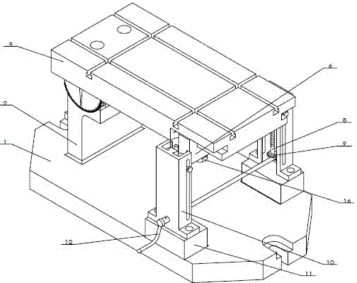
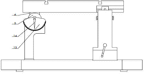
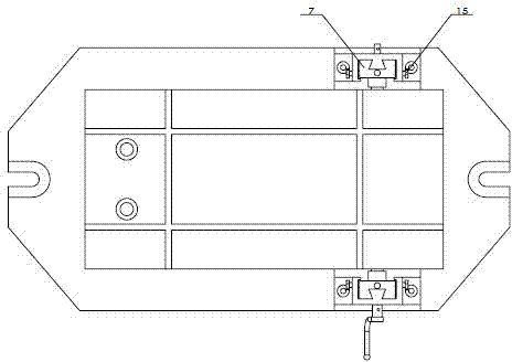
[0010] Fixtures such as figure 2 As shown, it includes the fixture base 1, the side wall 2, the shaft sleeve 3 is installed on the side wall 2 through bolts, the shaft 4 cooperates with the shaft sleeve 3 to form a hinge mechanism, the working plate 5 is connected with the shaft 4 through bolts, and the parts are connected through bolts and pressure plates. Fixed on the working board, the other end of the working board is connected with the shaft 6, the shaft 6 cooperates with the nut 7 with the shaft hole, the nut 7, the lead screw 8, the bevel gear 9, and the guide rail 10 form a nut screw mechanism, and the rocker arm 12 and the Bevel gear connection, by rotating the rocker arm, gear meshing, and thread transmission, the nut is pushed up and down to adjust the angle of the working plate.

[0011] When processing the workpiece, first rotate the rocker arm, read the required angle from the dial, and then tighten the clamping bolts 4×15 and 2×16. If the angle of the part pla...


PUM


Abstract

The invention relates to a milling machine fixture capable of adjusting an angle. The structure is simple, the operation is convenient, the problem that location of a plane with an angle in milling processing is complex in the existing milling processing is solved, the clamping time of a part is greatly shortened, and the processing efficiency is facilitated to be improved. The milling machine fixture capable of adjusting the angle mainly comprises a base, a side wall, a shaft sleeve, a shaft, a working plate, a guide rail, a nut, a screw, a bevel wheel and a rocker arm. The angle of the working plate is adjusted through the change of the height of the nut, so that the milling of planes of different angles and the processing of chutes of plate parts are met.

Description

technical field [0001] The invention relates to an angle-adjustable milling machine fixture, which belongs to the field of machinery. Background technique [0002] The fixture device is mainly used for milling parts with planes with different angles and plate parts with inclined grooves. [0003] In modern machining, when milling a plane with an angle, the required angle is usually measured with a ruler, and then fixed by using pads, bolts, and pressure plates. The clamping process is time-consuming and laborious, and the angle is difficult to guarantee. When the angle changes, it needs to be repeated. Carrying out above operation, production efficiency is difficult to improve. Contents of the invention [0004] The object of the present invention is to overcome the above-mentioned problems of the prior art, and provide a milling machine fixture with simple structure and convenient operation. [0005] The technical solution of the present invention is that the side wall ...

Claims


Application Information

Patent Timeline
IPC IPC(8): B23Q3/04
CPCB23Q3/04B23C2270/08B23Q3/062
Inventor 魏玉坤乔阳郭培全
Owner UNIV OF JINAN
Learn More