
Hybrid Power Driving Module Possessing Motor

A hybrid power and drive module technology, applied in the direction of electric power devices, power devices, electric components, etc., can solve the problem that the hybrid power drive module is not optimal, and achieve the effects of long-term operation efficiency improvement, low cost, and improved cooling efficiency

Active Publication Date: 2015-06-24
VOLKSWAGEN AG
View PDF7 Cites 1 Cited by
  • Summary
  • Abstract
  • Description
  • Claims
  • Application Information

AI Technical Summary

Problems solved by technology

[0005] Hybrid drive modules according to state of the art are not yet optimal

Method used


Image

  • Hybrid Power Driving Module Possessing Motor
  • Hybrid Power Driving Module Possessing Motor
  • Hybrid Power Driving Module Possessing Motor

Examples


Embodiment Construction

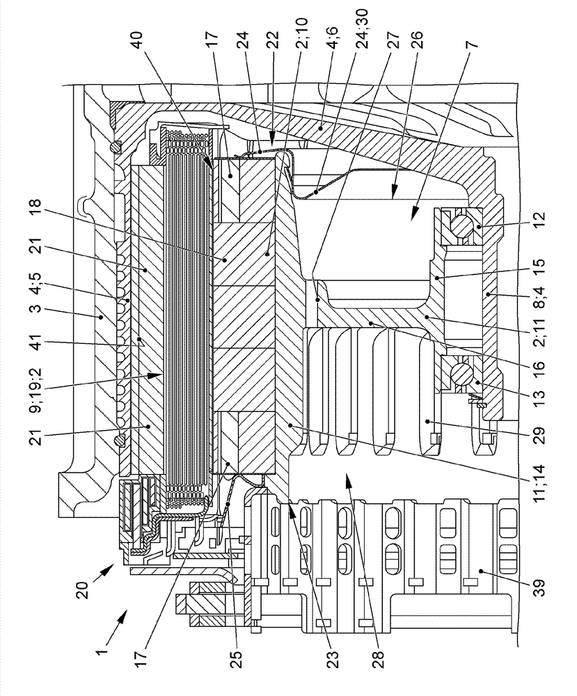
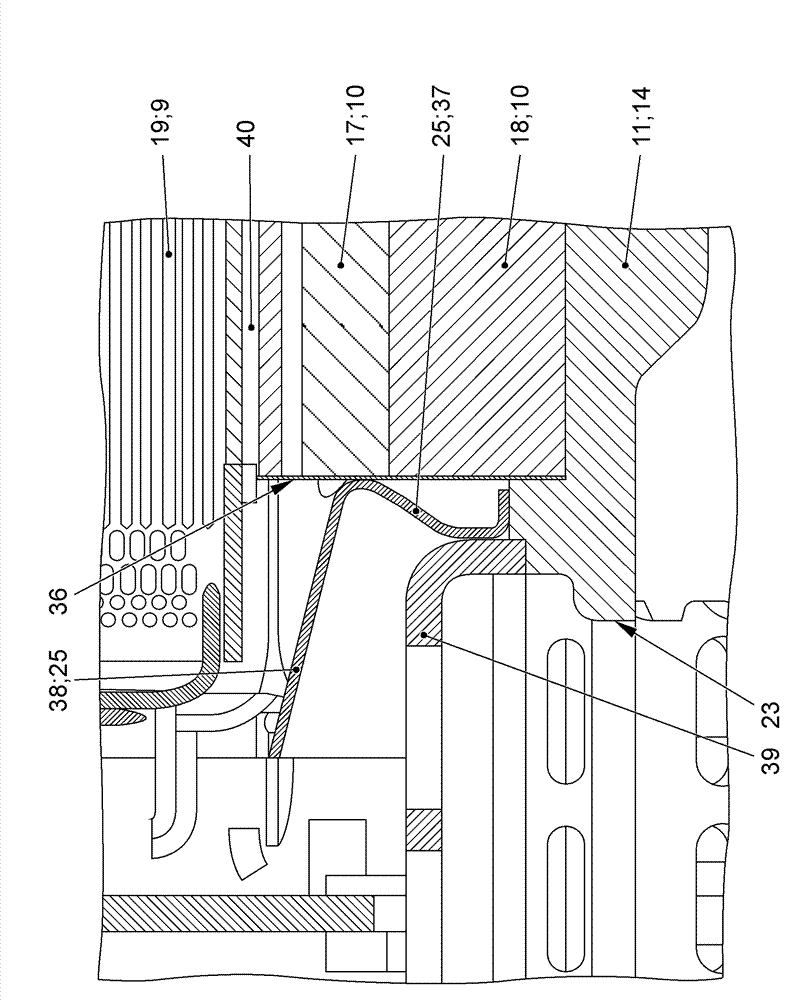
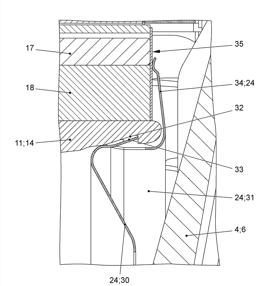
[0016] exist figure 1 The hybrid drive module 1 for the vehicle can clearly be seen in . The hybrid drive module 1 has an electric machine 2 . The electric machine 2 is arranged inside the clutch housing 3 . The electric machine 2 is also arranged inside a further inner housing 4 , the cooling housing. The housing 4 has a housing region 5 extending substantially in the axial direction. The housing region 5 serves here as a cooling housing. The side wall 6 extends inwardly adjacent to the housing region 5 . The housing 4 defines an oil chamber 7 , wherein the motor 2 is arranged inside the oil chamber 7 . The housing 4 also has a substantially hollow-cylindrical bearing region 8 . With its inner peripheral surface, the bearing region 8 delimits a shaft receptacle (not shown in detail), which is penetrated by a drive shaft (not shown). The bearing region 8 is here formed integrally with the side wall 6 and the housing region 5 . However, it should be noted that the corre...


PUM


Abstract

The present invention relates to a hybrid power driving module (1) possessing a motor (2), wherein the motor (2) is arranged on an oil cavity (7) and possesses a stator (9), a rotor (10) and a rotor support (11), and the rotor (10) and the rotor support (11) are connected without relative rotation. When the motor (2) operates, the trailing moment is reduced in at least following manners, namely, a first oil guide mechanism (24) is arranged at the end part of the motor (2), wherein with the help of the first oil guide mechanism (24), the oil can be guided to the other end part (23) of the motor (2) by penetrating an oil discharge opening (27) in the rotor support (11).

Description

technical field [0001] The invention relates to a hybrid drive module having the features of the preamble of claim 1 . Background technique [0002] A hybrid drive module in the form of a multi-stage clutch system for a hybrid vehicle is known from the prior art DE 10 2011 120 809 A1. The multistage clutch system has an oil cooling system, wherein the multistage clutch system has two wet starting clutches and a wet separating clutch on a common rotational shaft. The oil cooling system has a first oil supply path via the two starting clutches and a second oil supply path via the disconnect clutch. An electric machine in the form of an electric motor is arranged outside the multistage clutch system. The second oil supply path has an oil guide plate for guiding the oil flow, in particular via the gap between the two clutch carriers. The starter clutch is designed as a double clutch with two partial clutches. The electric machine is arranged in a common oil chamber with the ...

Claims


Application Information

Patent Timeline
Patent Type & Authority Applications(China)
IPC IPC(8): B60K6/26H02K9/19
CPCB60K6/26H02K9/19B60K2001/006
Inventor S.特里斯T.劳A.施特默
Owner VOLKSWAGEN AG
Learn More