
Sewing Machine Needle Bar Synchronous Rotation Mechanism

A technology of synchronous rotation and sewing machine needles, applied in the field of sewing machines, can solve the problems of incompatibility, low structural precision, unevenness, etc., and achieve the effects of eliminating transmission noise, improving sewing quality and improving pass rate.

Active Publication Date: 2017-11-21
ANHUI JIEYU SHOEMAKING MACHINERY TECH CO LTD
View PDF7 Cites 0 Cited by
  • Summary
  • Abstract
  • Description
  • Claims
  • Application Information

AI Technical Summary

Problems solved by technology

[0002] The traditional sewing mechanism generally includes an upper casing and a lower casing, an upper shaft motor and a needle bar mechanism installed on the upper casing, and an upper shaft motor and a needle bar mechanism that are respectively connected to the upper shaft motor and the needle bar mechanism in the upper casing. Shaft, as well as the lower shaft motor and the shuttle bed mechanism installed on the lower casing, are formed by the lower shaft which is installed in the lower casing and is respectively connected with the lower shaft motor and the shuttle bed transmission. The upper shaft is driven by the upper shaft motor to rotate, and the upper shaft The shaft drives the needle bar mechanism to move up and down to realize the up and down sewing action of the sewing needle. The lower shaft motor drives the lower shaft to rotate, and the lower shaft drives the shuttle bed mechanism to move to cooperate with the sewing needle for sewing operations. At this time, the needle bar cannot realize the corresponding rotation according to the sewing stitches at the same time, so that it is affected by the push and pull of the feeding mechanism when feeding, the force of the bottom thread and the upper thread is unbalanced when sewing at the thread hook position, and the sewing direction of the sewing needle cannot be adjusted. Keep consistent with the stitches to be sewn, which will eventually lead to defects such as loose, irregular, and uneven stitches
Especially when sewing irregular stitches, it is difficult for the stitching direction of the sewing needle to be consistent with the stitches set to be sewn, resulting in very loose, uneven, and uneven stitches that cannot be matched with Setting the stitches to be sewed to be completely consistent will seriously affect the appearance of the product and the sewing quality, and affect the overall quality of the product, resulting in a low pass rate of the product
Then there is a needle bar synchronous rotation mechanism that can keep the sewing direction of the sewing needle consistent with the stitches to be sewn. Its structure is that the motor and the motor base are installed on the casing, and the U-shaped motor shaft is specially customized. Both sides of the needle bar are made of flat surfaces, the needle bar slides up and down inside the motor shaft, and the rotation of the motor shaft drives the needle bar to rotate, because the needle bar and the motor shaft are sliding friction, and the motor shaft drives the needle bar to rotate, there is a radial pressure Therefore, during use, the needle bar and the motor shaft are prone to jamming and burning, and the gap between the needle bar and the motor shaft of this structure is relatively large, the overall structural accuracy is low, and it is difficult to lubricate and refuel.

Method used


Image

  • Sewing Machine Needle Bar Synchronous Rotation Mechanism
  • Sewing Machine Needle Bar Synchronous Rotation Mechanism

Examples


Embodiment Construction

[0011] The idea, specific structure and technical effects of the present invention will be further described below in conjunction with the accompanying drawings, so as to fully understand the purpose, features and effects of the present invention.

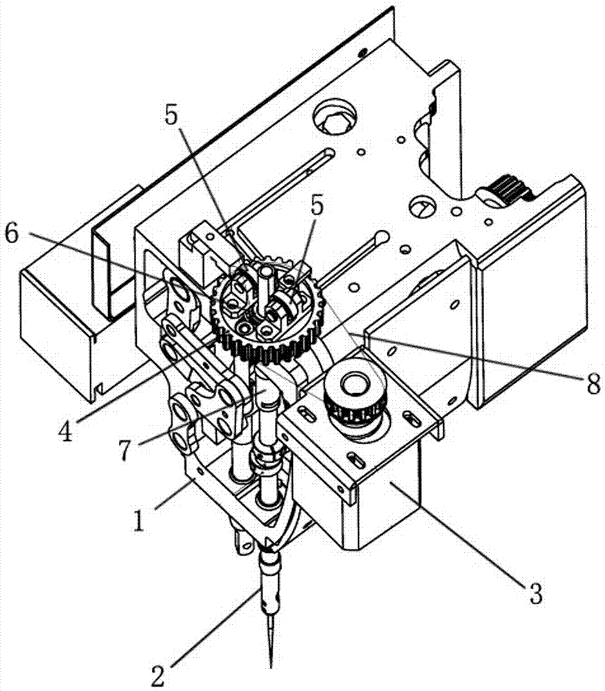
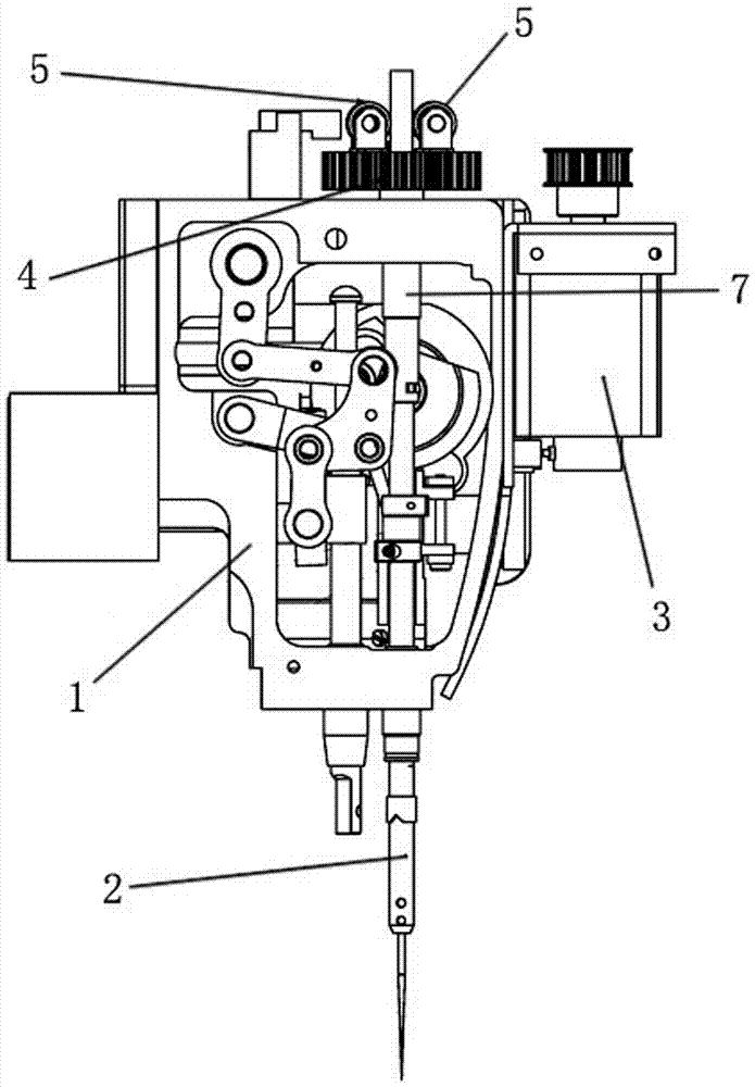
[0012] refer to figure 1 , 2 As shown, it is a schematic diagram of a preferred embodiment of the present invention. The present invention relates to a synchronous rotation mechanism of a needle bar of a sewing machine, which includes a needle bar 2 installed on an upper casing 1 for assembling machine needles, and a driving needle bar 2 rotating stepping motor 3, the upper end of the needle bar 2 is pierced and connected with a rotating synchronous gear 4, and a limit bearing 5 for clamping the needle bar 2 is arranged on the rotating synchronous gear 4, when the needle bar 2 moves up and down Form rolling friction with the limit bearing 5. In this embodiment, the contact surface of the needle bar 2 and the limit bearing 5 is a ...


PUM


Abstract

The invention relates to the technical field of sewing machines, in particular to a sewing machine needle bar synchronous rotation mechanism. The sewing machine needle bar synchronous rotation mechanism comprises a needle bar mounted on an upper machine shell and used for inserting of a sewing needle and a needle bar motor driving the needle bar to rotate. The upper end of the needle bar is connected with a rotating seat in a penetrating mode, a first bearing clamping the needle bar is arranged on the rotating seat, and the needle bar forms rolling friction with the first bearing when moving up and down; the rotating seat is assembled on a needle bar sleeve through a second bearing, the needle bar sleeve and the upper machine shell are fixedly connected together, and the rotating seat is in transmission connection with the needle bar motor. The needle bar is clamped through the two bearings, it is guaranteed that no gaps exist in transmission, sliding friction is changed to rolling friction, and friction force is lowered; a bearing seat is mounted on a synchronous belt wheel seat, the synchronous belt wheel seat and the sleeve on the needle bar are mounted together through a bearing, and concentricity of a rotating component and the needle bar is guaranteed; the structure is simple, design is ingenious and reasonable, product appearance and sewing quality can be greatly improved, and the percent of pass of products is improved.

Description

technical field [0001] The invention relates to the technical field of sewing machines, in particular to a sewing machine that can cooperate with a shuttle bed synchronous rotation mechanism on the sewing machine to perform synchronous rotation, so as to realize the synchronous rotation of the shuttle bed and the needle bar, so that the sewing direction of the sewing needle is consistent with the set sewing direction. The needle bar synchronous rotation mechanism keeps consistent stitches all the time. Background technique [0002] The traditional sewing mechanism generally includes an upper casing and a lower casing, an upper shaft motor and a needle bar mechanism installed on the upper casing, and an upper shaft motor and a needle bar mechanism that are respectively connected to the upper shaft motor and the needle bar mechanism in the upper casing. Shaft, as well as the lower shaft motor and the shuttle bed mechanism installed on the lower casing, are formed by the lower ...

Claims


Application Information

Patent Timeline
Patent Type & Authority Patents(China)
IPC IPC(8): D05B55/14
Inventor 王漫江
Owner ANHUI JIEYU SHOEMAKING MACHINERY TECH CO LTD
Learn More