Operating method for tractor clutch operating device with hydraulic assistance

A technology of clutch control and hydraulic power assist, which is applied to clutches, mechanical equipment, etc., can solve problems such as limited space for clutch friction plates, heavy clutch pedal control force, and reduced tractor control comfort, achieving novel design ideas and improved The effect of operating comfort and simple structure

Active Publication Date: 2015-06-24
LUOYANG WEILIN HYDRAULIC MACHINERY
View PDF5 Cites 17 Cited by
  • Summary
  • Abstract
  • Description
  • Claims
  • Application Information

AI Technical Summary

Problems solved by technology

[0002] At present, the clutch disengagement systems of many tractors use mechanical operating mechanisms. With the continuous improvement of tractor power, the requirements for the torque transmission capacity of the clutch are also higher. To increase the torque reserve coefficient of the clutch, it is usually used to increase the clutch There are two ways to increase the diameter of the friction plate and increase the compression force of the disc spring. However, due to structural limitations, the space for increasing the diameter of the clutch friction plate is very limited, so the method of increasing the compression force of the disc spring is often used to increase the clutch torque. Reserve coefficient, the increase of disc spring pressing force leads to heavy clutch pedal operating force, increases the labor intensity of the driver, and greatly reduces the tractor's operating comfort

Method used


Image

  • Operating method for tractor clutch operating device with hydraulic assistance

Examples


Embodiment 1

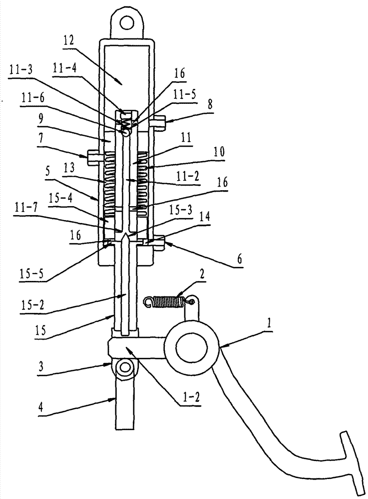
[0017] The clutch pedal 1 is connected with the fixed bracket of the cab through the return spring 2, the top plate 1-2 of the clutch pedal 1 is arranged in the U-shaped connecting fork 3, and the U-shaped opening of the connecting fork 3 is connected with the clutch pull rod 4 through the connecting pin, and connected The middle part of the fork 3 is connected with the piston rod 15 of the booster cylinder 5; the booster cylinder 5 is provided with an oil inlet 6, an oil outlet 7, and an oil return port 8 from bottom to top, between the oil inlet 6 and the output port of the steering constant flow pump Install the hose, install the hose between the oil outlet 7 and the oil inlet of the hydraulic steering gear, install the hose between the oil return port 8 and the oil inlet of the steering constant flow pump oil tank, set the lifting lug above the power cylinder 5, and set the power cylinder Blocking block 9 is set in the middle of 5, oil return cavity 12 is formed above block...

Embodiment 2

[0019] When the clutch pedal 1 is not stepped on, the throttle valve 15-2 is in the open state, and the hydraulic oil in the steering constant flow pump enters the lower chamber 13 through the oil inlet 6, and flows into the piston from the oil hole 16 of the connecting block 15-5. 15-4, it enters the oil passage 11-2 of the valve stem 11 upwards, enters the upper cavity 13 through the oil holes 16 on both sides below the valve stem 11, flows into the hydraulic steering gear through the oil outlet 7, and flows into the oil inlet 6. Pressure is less than 3 MPa, and the oil pressure of upper chamber 13 and lower chamber 14 in the booster cylinder 5 is equal, so that the pressure in the booster cylinder 5 remains balanced.

Embodiment 3

[0021]During normal use, step on the clutch pedal 1, the top plate 1-2 of the clutch pedal 1 pushes up the throttle valve 15-2 in the piston rod 15, the throttle valve 15-2 is in a semi-closed state, and the throttle valve 15-2 The conical head 15-3 enters the bell mouth 11-7 of the valve stem 11 upwards, the oil pressure entering the oil inlet 6 is 3-10 MPa, and the hydraulic oil in the piston 15-4 enters the oil passage 11- 2 decreases, the flow flowing into the upper chamber 13 decreases, so that the oil pressure in the lower chamber 14 increases, pushing the piston 15-4 to move upward along the inner wall of the booster cylinder 5, and the piston 15-4 drives the piston rod 15 to move upward , the piston rod 15 drives the clutch rod 4 through the connecting fork 3 to generate an upward pulling force; the throttle valve 15-2 moves up and down to control the flow flowing into the oil passage 11-2 to generate different thrusts, and the conical head 15-3 is close to the bell mou...


PUM


Abstract

The invention discloses an operating method for a tractor clutch operating device with hydraulic assistance. A booster cylinder is connected with a clutch pull rod through a clevis by a clutch pedal, an output pipeline of a steering constant flow pump of a tractor provides pressure for the booster cylinder, and a piston rod of the booster cylinder is connected with the clutch pull rod through the clevis. When a driver steps on the clutch pedal, firstly power is provided for a throttling valve in the piston rod to enable an upper cavity and a lower cavity in an assistance oil cylinder to generate a pressure difference, the piston rod is pushed to pull the clutch pull rod, the clutch is separated, the easy control of the clutch is achieved, the torque reserve coefficient of the clutch is increased, the operating force of the driver is reduced, and the operating comfort of the driver is improved.

Description

technical field [0001] The invention relates to the technical field of tractor clutch control, in particular to an operation method of a tractor clutch control device with hydraulic power assist. Background technique [0002] At present, the clutch disengagement systems of many tractors use mechanical operating mechanisms. With the continuous improvement of tractor power, the requirements for the torque transmission capacity of the clutch are also higher. To increase the torque reserve coefficient of the clutch, it is usually used to increase the clutch There are two ways to increase the diameter of the friction plate and increase the compression force of the disc spring. However, due to structural limitations, the space for increasing the diameter of the clutch friction plate is very limited, so the method of increasing the compression force of the disc spring is often used to increase the clutch torque. Reserve coefficient, the increase of disc spring pressing force leads ...

Claims


Application Information

Patent Timeline
Patent Type & Authority Applications(China)
IPC IPC(8): F16D48/04
CPCF16D48/04
Inventor 盛雷盛怀林
Owner LUOYANG WEILIN HYDRAULIC MACHINERY
Why Eureka
Try Eureka