
Bio-directional common optical path distributed fiber optic interferometer

A technology of distributed optical fiber and interferometer, which is applied in the field of optical fiber interferometer, can solve the problems of reducing the length of detection distance and the tight use of optical fiber in communication optical cables, and achieve the effects of increased signal strength, low cost and easy implementation

Inactive Publication Date: 2015-06-24
浙江诺可电子科技发展有限公司
View PDF6 Cites 6 Cited by
  • Summary
  • Abstract
  • Description
  • Claims
  • Application Information

AI Technical Summary

Problems solved by technology

However, this two-way common optical path distributed optical fiber interferometer needs to occupy four optical fibers in the communication optical cable, and the use of optical fibers in the communication optical cable is becoming more and more tight in actual engineering, which increases the practical difficulty of optical fiber distribution; on the other hand, Using this two-way common optical path distributed fiber interferometer, the optical signal received at the receiving end is weak, and the weak optical signal received will reduce the length of the detection distance

Method used


Image

  • Bio-directional common optical path distributed fiber optic interferometer
  • Bio-directional common optical path distributed fiber optic interferometer

Examples


Embodiment Construction

[0016] The present invention will be further described in detail below in conjunction with the accompanying drawings and embodiments.

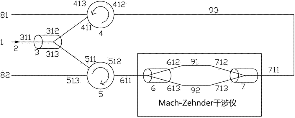
[0017] A kind of two-way common optical path distributed optical fiber interferometer proposed by the present invention, such as figure 1 As shown, it includes a fiber isolator 2, a first fiber optic splitter 3, a first fiber optic circulator 4, a second fiber optic circulator 5, and the same second fiber optic splitter 7 and third fiber optic splitter 6 that are independent of polarization 1. The Mach-Zehnder interferometer with equal arm length formed by the two sensing fibers 91 and 92 in the communication optical cable, in order to make the additional phase difference of the two interference signals output from the two ends of the Mach-Zehnder interferometer consistent, it is required The light in the positive and negative directions respectively enters the second optical fiber splitter 7 and the third optical fiber splitter 6 in the Mach-...


PUM


Abstract

The invention discloses a bio-directional common optical path distributed fiber optic interferometer. The bio-directional common optical path distributed fiber optic interferometer comprises a fiber optic isolator, a first fiber optic optical splitter, a Mach-Zehnder interferometer composed of a same second fiber optic optical splitter and a third fiber optic optical splitter, a first fiber optic circulator and a second fiber optic circulator; light enters the first fiber optic optical splitter after passing through the fiber optic isolator, the light is divided into two paths of the light with the same light intensity, one path of the light enters the second fiber optic optical splitter after passing through the first fiber optic circulator, the other path of the light enters the third fiber optic optical splitter after passing through the second fiber optic circulator, the light in the positive and the light in the negative directions are connected directly through a straight-through arm, one path of interference signals output by the third fiber optic optical splitter enters a first receiving end after passing through the first fiber optic circulator, the other path of the interference signals output by the third fiber optic optical splitter enters a second receiving end after passing through the second fiber optic circulator, and the waveforms of the two paths of the interference signals are consistent. The bio-directional common optical path distributed fiber optic interferometer has the advantages that the number of occupied cores of fiber optic in communication optical cables is reduced, and the signal intensity of the optical signals received by the receiving ends is increased greatly.

Description

technical field [0001] The invention relates to an optical fiber interferometer, in particular to a bidirectional common optical path distributed optical fiber interferometer. Background technique [0002] Optical fiber interferometer is a basic optical structure in optical fiber sensing and detection technology, and is the key technology to achieve high sensitivity and high precision measurement. Traditional optical fiber interferometers mainly include Michelson interferometer, Fabry-Perot interferometer, ring cavity interferometer and Mach-Zehnder interferometer. Since these optical fiber interferometers have a unidirectional structure with one input at one end and output at one end, the light interference obtained at the output end The signal is the integral of all disturbances distributed along the fiber, and the disturbance information at a specific distance cannot be separated, so these fiber interferometers cannot achieve distributed detection. [0003] With the incr...

Claims


Application Information

Patent Timeline
IPC IPC(8): G01D5/26
Inventor 张美丽陈兆麟吕明
Owner 浙江诺可电子科技发展有限公司
Learn More