Horizontal axis type sediment runoff gauge

A sediment and runoff technology, which is applied in the application of electromagnetic flowmeters to detect fluid flow, volume/mass flow generated by electromagnetic effects, etc., can solve the problems of high cost, large starting and running flow, incompatibility, etc., and achieves simple structure, The effect of saving manpower and equipment resources and improving the accuracy of monitoring

Inactive Publication Date: 2015-06-24
周庆华 +1
View PDF11 Cites 2 Cited by
  • Summary
  • Abstract
  • Description
  • Claims
  • Application Information

AI Technical Summary

Problems solved by technology

However, the construction of collecting facilities (collecting pool or collecting tube) is more complicated. One is the volume of the collecting pool. If the maximum rainstorm runoff is calculated according to the maximum rainstorm runoff of a 24-hour rainstorm once in five years, the volume of the collecting pool must be at least 5 cubic meters. , the amount of engineering is large, and the quality and accuracy are difficult to guarantee. If a collecting bucket or a splitting bucket is used, the investment is large and the cost is high, and maintenance is required every year.
In terms of operation, every time it rains, technicians need to observe the rainfall on the spot, replace the self-recording paper, take water, filter, dry and weigh, clean the sump (bucket), etc., which is labor-intensive and time-consuming. It is also difficult to raise management and operation fees, so many observation areas cannot be supported after less than a few years of operation, and have to give up halfway
[0006] In order to improve the automation and accuracy of water erosion community monitoring, based on the improvement of traditional monitoring methods, Chinese patent CN103698159A discloses a rainfall-triggered runoff automatic sampler and its method, and Chinese patent CN201607350U discloses a low-interference slope runoff sampling device, the devices disclosed in the above two patents are used for sampling and sediment monitoring of the runoff section, but lack of monitoring of runoff
The reasons are as follows: first, the runoff of the water erosion area contains a large amount of sediment, and the commonly used flow detection and monitoring equipment, such as flow meters, are easy to block and require a large flow rate for start-up and operation; Puller flow meters, etc., are not compatible with sampling and sediment monitoring equipment, and require additional doses, which increases labor and equipment input costs

Method used


Image

  • Horizontal axis type sediment runoff gauge
  • Horizontal axis type sediment runoff gauge
  • Horizontal axis type sediment runoff gauge

Examples


Embodiment 1

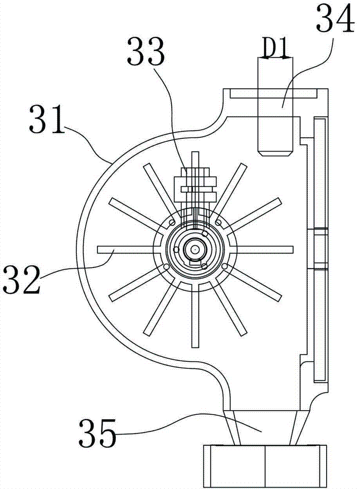
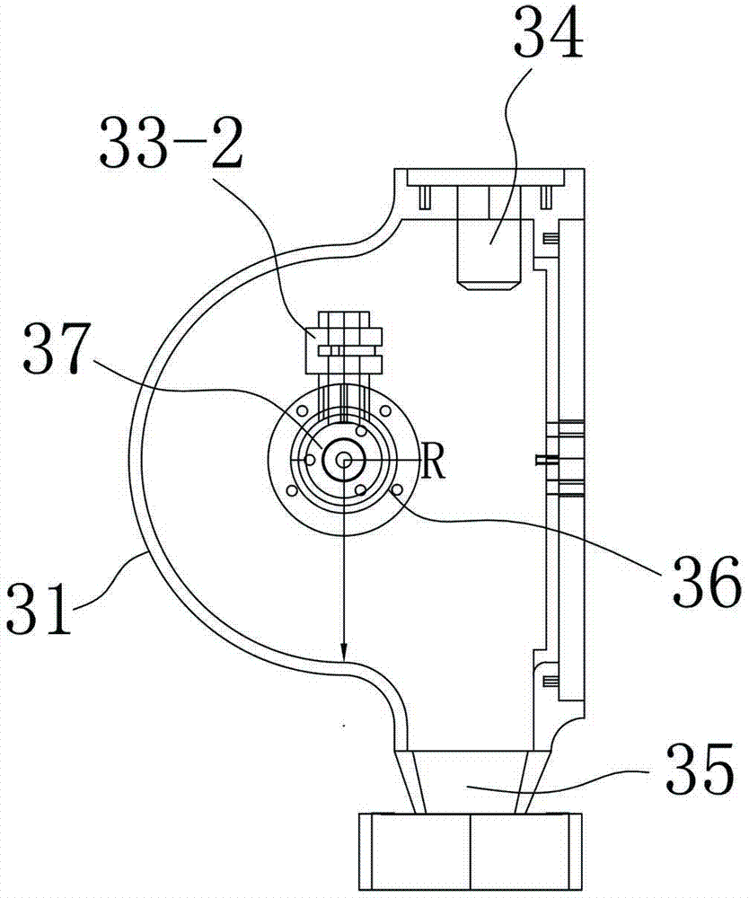
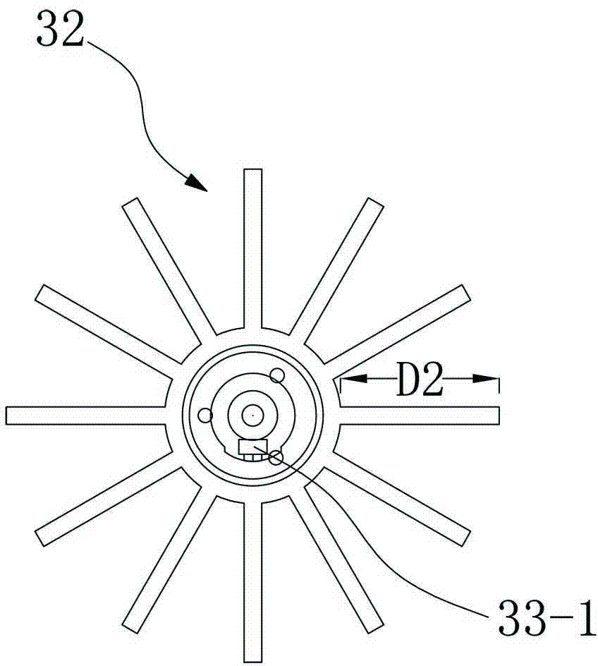
[0042] as attached Figure 1~3 As shown, the horizontal axis sediment runoff meter of the present invention includes a casing 31 provided with a water inlet 34 and a water outlet 35 and an impeller 32 arranged in the casing 31, and the casing 31 is provided with a measuring instrument. The sensing device 33 of the number of rotations of the impeller 32; the impeller 32 is arranged in the housing 31 through the bearing 36, and fan blades are uniformly arranged on the impeller; The magnetic induction body 33-1 on 32 and the magnetic induction sensor 33-2 corresponding to the magnetic induction body 33-1 are arranged on the housing 31, and the width D1 of the water inlet 34 is smaller than the width D2 of the fan blade.

[0043] The number of the fan blades is 12, which are evenly arranged outside the circumference of the bearing 36 . The center of the cavity of the housing 31 is provided with a bearing seat 37, and the bearing 36 is arranged on the bearing seat 37; the center of ...

Embodiment 2~5

[0048] The devices in Examples 2-5 are basically the same as those in Example 1, the only difference being the length and width of the fan blades, and the accuracy of the measured muddy water runoff was specifically monitored. The monitored water was added with 20% solid sediment, and the specific results are shown in Table 1. Where L1 is the length of the housing cavity, L2 is the length of the fan blade, D2 is the width of the fan blade, and R is the radius of the housing cavity.

[0049]

[0050] According to the above experimental data, commercially available flowmeters cannot complete the monitoring due to the blockage of sediment; by adopting embodiments 1 to 5 of the present invention, the monitoring of sediment can be realized, and the accuracy can reach more than 85%; by optimizing the housing The proportional relationship between the length of the cavity, the length of the fan blade, the width of the fan blade and the radius of the housing cavity can further impro...

Embodiment 6

[0052] as attached Figure 4 As shown, the horizontal axis sediment runoff meter of the present invention includes a casing 31 provided with a water inlet 34 and a water outlet 35 and an impeller 32 arranged in the casing 31, and the casing 31 is provided with a measuring instrument. The sensing device 33 of the number of rotations of the impeller 32; the impeller 32 is arranged in the housing 31 through the bearing 36, and fan blades are uniformly arranged on the impeller; the sensing device 33 includes a The magnetic induction body 33 - 1 on the top and the magnetic induction sensor 33 - 2 corresponding to the magnetic induction body 33 - 1 arranged on the housing 31 , the width of the water inlet 34 is smaller than the width of the fan blade. The water inlet 34 is provided with several thin tubes 39 with a diameter of 1-2 cm. A buffer pipe 38 is disposed below the housing 31 , and the water outlet 35 is disposed on a side of the buffer pipe 38 .

[0053] The number of the...


PUM


Abstract

The invention relates to a horizontal axis type sediment runoff gauge. The horizontal axis type sediment runoff gauge comprises a shell and an impeller, wherein the shell is provided with a water inlet and a water outlet, the impeller is arranged in the shell, and the shell is provided with a sencing device used for measuring the rotating turns of the impeller. The impeller is arranged in the shell through a bearing and evenly provided with fan blades. The sensing device comprises a magnetic induction body and a magnetic induction sensor, wherein the magnetic induction body is arranged on the impeller, the magnetic induction sensor is arranged on the shell and corresponds to the magnetic induction body, and the width of the water inlet is smaller than the width of the fan blades. According to the horizontal axis type sediment runoff gauge, the rotation of the impeller in contact with inlet water is converted into digital signals through electromagnetic induction, and thus the measurement of the runoff volume is achieved; the accurate degree of measurement can be improved by optimizing the structure of the water inlet and the parameter of the fan blades of the impeller, and precision can be improved to 90%. The horizontal axis type sediment runoff gauge can be connected into an existing sediment device to achieve monitoring, and compensate for the defect that an existing sampling device cannot monitor the runoff volume.

Description

technical field [0001] The invention relates to a horizontal axis sediment runoff meter. Background technique [0002] The rainfall, runoff, and sediment observation experiments in water erosion plots are an important way to study the law of water and soil loss and the benefits of soil and water conservation, and also one of the important means to carry out monitoring of water and soil conservation. The infrastructure for monitoring plots includes water collection plots (standard The projected area of ​​the catchment area of ​​the water-eroded community is 100 square meters, the projected length of the water-retaining enclosure is 20 meters, and the width is 5 meters), collecting tanks and collecting tanks (or collecting barrels), etc. Observation and measurement instruments mainly include rain gauges, water fetchers, dryers, balances, etc. [0003] Among them, the main contents of soil and water conservation observation in the water erosion area include: rainfall, runoff a...

Claims


Application Information

Patent Timeline
Patent Type & Authority Applications(China)
IPC IPC(8): G01F1/58
Inventor 周庆华王凤翔张卫平相征
Owner 周庆华
Why Eureka
Try Eureka