Auxiliary jet-flow system for controlling high speed wind tunnel transonic flow field

A high-speed wind tunnel and auxiliary control technology, applied in the field of high-speed wind tunnel sub-transonic flow field control, experimental aerodynamics, and sub-transonic wind tunnel flow field control, can solve problems such as complex structure and difficult installation, and achieve The effect of high control precision, small structural damage and simple control method

Active Publication Date: 2015-06-24
CHINA ACAD OF AEROSPACE AERODYNAMICS
View PDF8 Cites 13 Cited by
  • Summary
  • Abstract
  • Description
  • Claims
  • Application Information

AI Technical Summary

Benefits of technology

This patented technology allows for precise measurement of sub-subsonic flows without affecting other parts or causing damages during testing. It also provides an efficient way to adjust the amount of fluid being injected into different areas within the tested part while maintaining its stability. Additionally, it uses a special design that improves the durability of the weatherproof membrane over which the water passes when there are no rainwater conditions. Overall, this new technology simplifies the process of controlling fluids inside wind tunnels and ensures stable operation under various environmental factors such as temperature changes.

Problems solved by technology

This patented describes how accurate testing can occur for airplanes at different speeds depending on their specific needs. By regulating both the amount of intake fluid entering the engine's fan case (flow) and the size of an exit port(open), the system ensures consistency between tested conditions and results from various factors like altitude, atmospheric temperature, humidity levels, etc., which may vary over short periods of time. Additionally, there has been research into improving the performance of certain types of flight vehicles without compromising safety standards. These issues include reducing noise emissions caused by turbulence within the vehicle cabin, increasing fuel efficiency, minimizing wear and tear damage, and enhancing passenger comfort level. Overall, these technical problem addressed in the patents involve accurately measuring and controllably manipulating flows in realistic environments while maintaining strict requirements imposed upon them.

Method used


Image

  • Auxiliary jet-flow system for controlling high speed wind tunnel transonic flow field
  • Auxiliary jet-flow system for controlling high speed wind tunnel transonic flow field
  • Auxiliary jet-flow system for controlling high speed wind tunnel transonic flow field

Examples


Embodiment Construction

[0028] In order to make the above objects, features and advantages of the present invention more comprehensible, specific implementations of the present invention will be described in detail below in conjunction with the accompanying drawings.

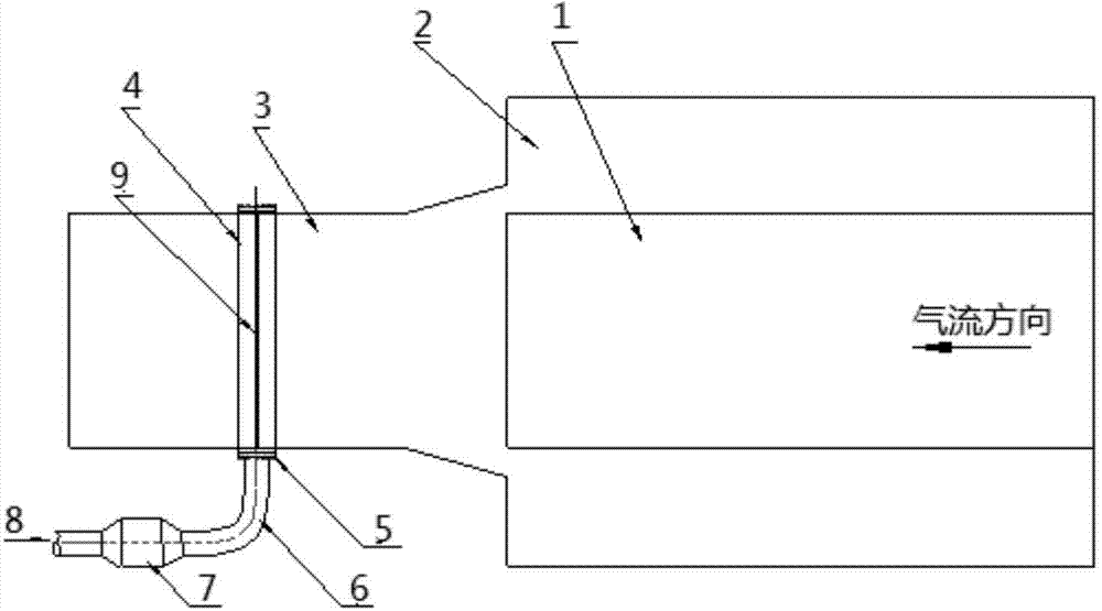
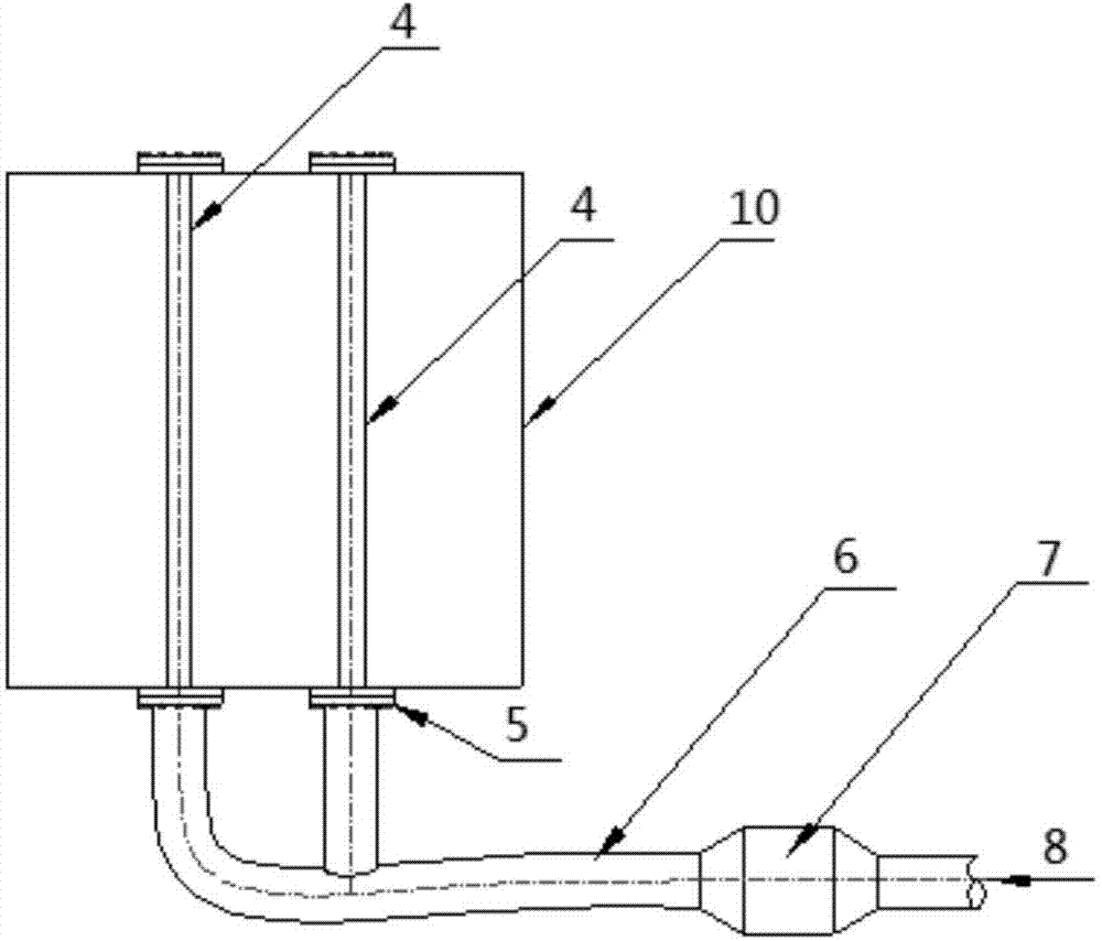
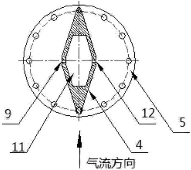
[0029] see figure 1 , figure 2 , image 3 with Figure 4 , the present invention provides a jet flow system for auxiliary control of the sub-transonic flow field in a high-speed wind tunnel, including: a jet flow device 4, which is installed in the second throat regulating plate area 3 of the wind tunnel, and the jet flow device 4 is in the form of Long and straight, there is a gas channel 11 inside, and the jet flow device has a symmetrical plane H on the airflow direction parallel to the wind tunnel; The two sides are distributed symmetrically with respect to the symmetrical plane, and the airflow ejection direction of each spray hole is perpendicular to the symmetrical plane H; the ventilation duct 6, which communicates with the...


PUM


Abstract

The invention discloses an auxiliary jet-flow system for controlling a high speed wind tunnel transonic flow field. The system comprises a jet-flow device, two rows of jet-flow holes and a ventilation pipeline, wherein the jet-flow device is installed in a second throat adjustment sheet area of a wind tunnel, the jet-flow device is in a long and straight shape, an air channel is formed in the jet-flow device, and the jet-flow device has a symmetry plane in the air flow direction parallel to the wind tunnel; the two rows of the jet-flow holes are formed in the two sides of the jet-flow device respectively, the jet-flow holes are distributed symmetrically relative to the symmetry plane, and the ejecting direction of air flow of each jet-flow hole is perpendicular to the symmetry plane; the ventilation pipeline is communicated with the jet-flow device and located outside the wind tunnel, the ventilation pipeline is provided with a regulating valve used for regulating the air flow pressure of the jet-flow holes, and the ventilation pipeline is communicated to an air source. According to the system, the pressure regulating valve is adopted for controlling the pressure of the air flow of the jet-flow holes, the control mode is simple, and the control accuracy is high.

Description


Claims


Application Information

Patent Timeline
Owner CHINA ACAD OF AEROSPACE AERODYNAMICS
Why Eureka
Try Eureka